Thanks Ray,
This will probably be the last post for a while on the BT30 spindle because I have other work to complete before I can re-focus on this project. The gripper is a central character in this play so really making and testing the gripper mechanism could be considered part of the feasibility study. Put in simple terms; no gripper - no spindle. So I wanted to accomplish a working gripper before I dedicate the time and resources to a spindle/drawbar project.
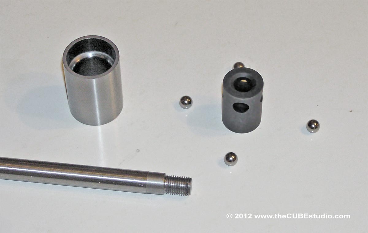
Below are photos of the completed gripper parts. After heat treating the sleeve was tempered only slightly for max hardness. The ball holder was tempered to a typical 'cold work' spec for S7 After heat treat, the parts were pickled and blasted to remove scale. Small S7 parts and A2 parts are air quenched and typically there is only minor distortion. The ball holder was fine and the threads still worked perfectly, so it just got a black oxide treatment and was completed
The sleeve, as expected, had minor distortion. The ID does not have to be perfectly concentric and the ball holder still slid nicely in the sleeve, so the ID was simply re polished for smooth action and low wear on the balls. However, again as expected, the OD had to be ground to bring it to size and concentricity for pressing into the spindle nose.
My research turned up a figure of around 600lbs drawbar tension for BT30, so I will design the mechanism for 600 lb pull and 1000lb release on 100psi shop air. The cylinder is rated to 200psi, so there will be plenty of headroom. I will test the gripper at 2,500lb pull so that in case I have to go up to 1,000 pull on the holding force, I will still have a 2.5x test.
Making the new mill spindle will be simple compared to the new 4th axis spindle that I recently completed. There are decisions to be made about cartridge vs open frame and of course the type of bearings.
OK, on to the photos. First is just a shot of the completed gripper pieces:

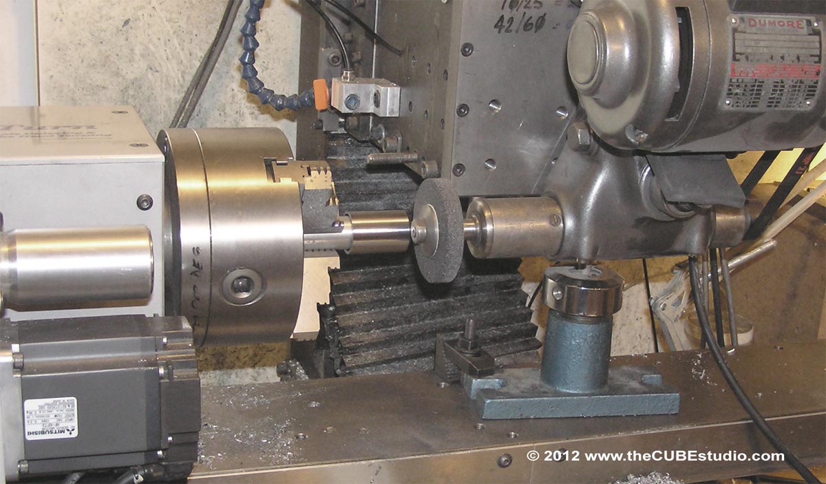
This is a shot of the setup for grinding the OD of the sleeve. The sleeve is bolted to the same custom made mandrel for both machining and grinding the OD.

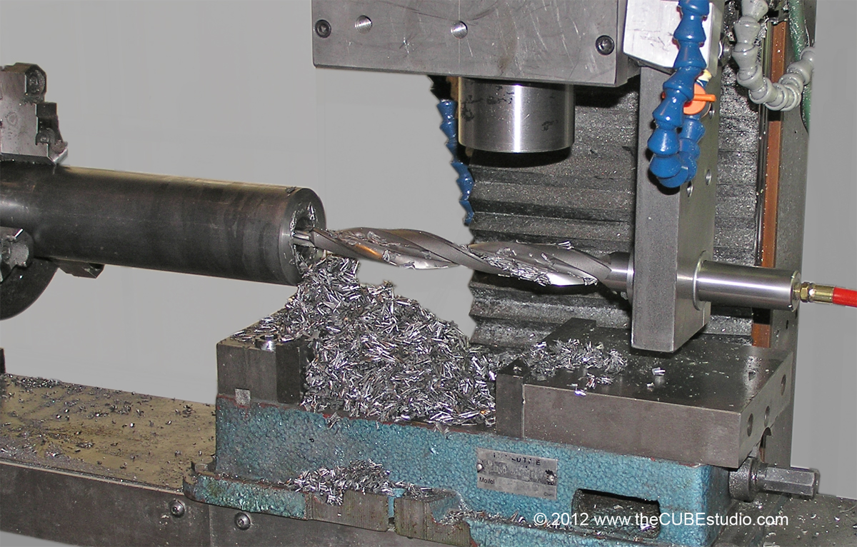
This next shot is the 4th axis spindle getting 'cored', but a similar operation, albeit not nearly as big a hole, will be done on the new mill spindle. This is the toughext part of the job. Once that hole is thru the piece, the rest is relatively easy. I was only barely able to get this hole made. The 4th axis motor stalled several times and the stress twisted the mill column. The final drive on the current 4th axis is 5.76:1 and the column is bolted together and not fully boxed (this is just a temporary mill). To resolve, the new 4th axis final drive is 12:1 and the column (now realigned) will be welded and boxed in. This will defeat my 'easy shipping' plan for this mill, but there are no other options.
