I have been working on the control side of things so there is not much to report on the hardware. As I mentioned earlier, the control scheme is really the more difficult part of the ATC project. The prototypes in this thread are being incorporated into an all new CNC converted IH milling machine and the controls will have the ATC fully integrated. I will only be posting here the portions of that project that are directly related to the BT30 spindle and the ATC.
To that end, I have just completed the computer, motion control setup and interfacing for the project. On Ray's recommendation, I went with the K-flop board over the smoothstepper. While the Kflop board is far from the 'plug and play' that I was hoping for, eventually (with very prompt, accurate and well targeted support from Dynomotion on their Yahoo group) I did get it going. A major caveat with the K-flop is that 'most' of it is 3.3V only. I got caught with my pants down on this because I only read the K-flop spec to the point where it said '5V tolerant', however, when I went to integrate the board and read the entire spec, I discovered that only a few of the pins are 5V tolerant and the rest are 3.3V ONLY, which was bad enough, but they also are limited to a tiny 10mA current. I now have 7 different boards and many of them had to be redesigned to work with the K-flop, and I had to make up a special batch of boards for this project . . a rather large task that I had not anticipated.

Although there is essentially zero cutting time on the system, so far it has not exhibited the USB smoothstepper's bad manners, so I am encouraged that it will be a good solution for the initial MACH3 support as well as hosting some or all of the ATC control in the future. The K-flop is running a total of 7 axis; 3 linear, 3 rotary and the servo powered spindle.
At this time, my InTurn™ 4th axis motor controller is hosting the ATC controls. The motor controller has a multi task board (swapaxis, digital signal synthesizer, line driver) that is mounted in the CNC computer so for the sake of simplifying the external cabling, I ran all of the controllers cables to the CNC computer. From that central point, all of the cabling runs to two large enclosures which house the EIGHT Mitsubishi AC servo drives and a bank of 12 relays. From the enclosures, one set of cables goes to the head and include the spindle servo cables, the ATC cables and all sensor cables. The second enclosure has a set of cables that run to the mill base and contain the X,Y, and Z axis, the InTurn™ 4th axis, 5th axis servo cabling as well as relay and sensor cables.
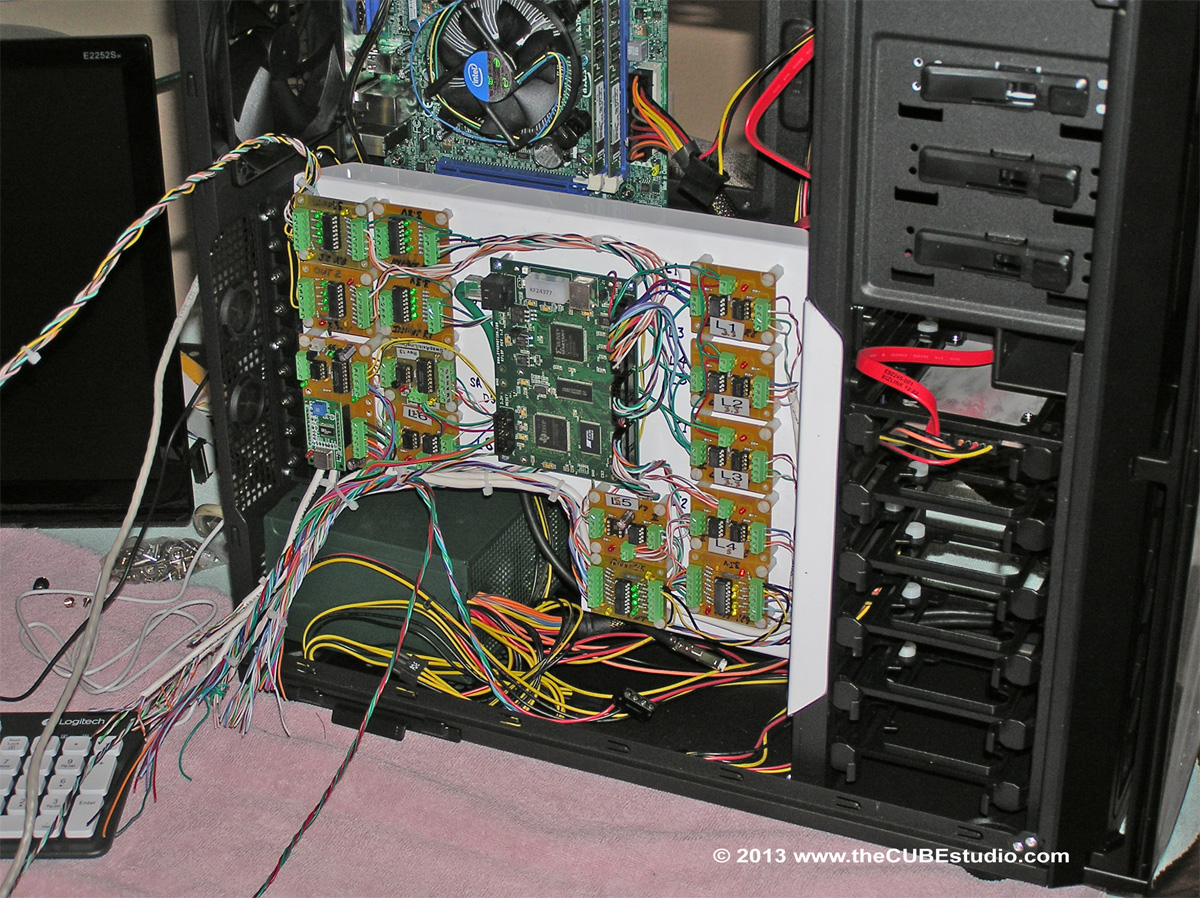
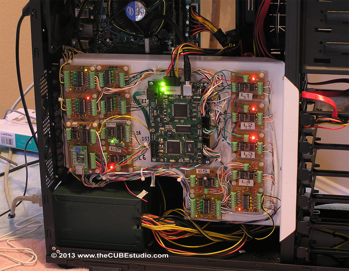
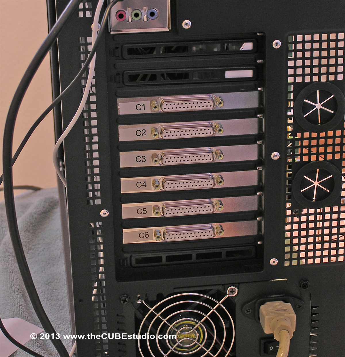
The first step in the overall task is now completed. I fabricated an aluminium 'mezzanine' plate to mount the motion control board and all of the supporting interface boards. This is mounted in a large server case with the dozens of wires collected into SIX connectors on the back of the case. In the planned arrangement, the computer will be on or near the floor with approx 6 feet and 10 feet cable runs to the two wall mounted drive enclosures. Cable runs from the enclosures to the mill will be 8 to 10 feet. All of the servo cables are Mitsubishi factory made parts. Pneumatic valves and mechanical solenoids run at 12V and the optical sensors and limit switches run at 24V to help with noise immunity.
I am very happy to have the electronics portion (which I do not enjoy) completed so that I can now move on the the mechanics of the conversion (which is the fun stuff).
This is the mezzanine with all of the goodies installed and wired up, but without the external connectors

Next is the completed setup final install and running

This is the back of the server case showing the 6 DB25 connectors needed to get all of the wires where they are going.
