Hello Guest it is March 28, 2024, 10:12:08 AM

Author Topic: outputs 4 and 5 on CSMIO  (Read 26036 times)

0 Members and 1 Guest are viewing this topic.

Offline ger21

*
  • *
  •  6,295 6,295
    • View Profile
    • The CNC Woodworker
Re: outputs 4 and 5 on CSMIO
« Reply #20 on: July 28, 2014, 07:15:28 AM »
On the Spindle Tab, "Use Spindle Motor Output" under Motor Control should not be checked, according to page 43 of the manual.
Gerry

2010 Screenset
http://www.thecncwoodworker.com/2010.html

JointCAM Dovetail and Box Joint software
http://www.g-forcecnc.com/jointcam.html

Offline mmoe

*
  •  23 23
    • View Profile
Re: outputs 4 and 5 on CSMIO
« Reply #21 on: July 28, 2014, 01:14:36 PM »
If you hooked up the relays as you depicted in the first page, the problem likely stems from the wiring more so than the configuration. You need to fix the wiring first or you'll be spinning your wheels. For that matter, it's entirely possible that you have damaged the controller if you've hooked it up the way you have shown. Putting a 5 volt power supply positive to the common of the outputs is essentially sending 5 volts backwards through the outputs system, where the CSMIO outputs are meant to operate at 24 volts and that pin is essentially the "ground" (though ground is not a good term for a common as they are technically different). Here's a correction to the diagram:

RelayCorrections by mmoe5150, on Flickr


The problem is several things. First, CSMIO outputs should be used to turn relays on and off using a 24volt DC power supply (same one providing 24 volts to the controller itself is fine). At the CSMIO controller, you need to supply 24VDC to a specific pin that will provide power for the outputs. The outputs then forwards the 24VDC signal to the relay when it is turned on. The relay is activated by running 24 volts DC through the coil (you must have a 24 VDC coil relay, so not all relays are the same!). The coil is also connected to the CSMIO at the outputs "common" to complete the coil circuit. The switch portion of the relay is used to forward voltage to a load, or in the case of an "enable/disable" loop, you are forwarding a voltage as a signal. Regardless of what the load or signal is, the coil is all that is run by CSMIO. If you need 5 volts to enable/disable your Gecko drive, you must have a separate power supply that runs 5 volts to the relay switch, which will then be forwarded to the drive from the relay when the CSMIO activates the relay's coil. This 5 volts does not ever get run through the CSMIO, it is run through the relay. Similarly, you can send 110 VAC, 220 VAC, 24 VDC, 10 VDC, 5VDC or whatever else you might need through the relay switch, which is turned on and off by the CSMIO output. The only limitation then is that the relay is going to be rated for somewhere around 5amp to 12 amps, depending on the relay.

Re-read the manual regarding how to properly configure an output from the controller. Hope that helps, and feel free to ask if you don't understand.

Offline mmoe

*
  •  23 23
    • View Profile
Re: outputs 4 and 5 on CSMIO
« Reply #22 on: July 28, 2014, 03:20:03 PM »
Here's a quick diagram I did a while back that shows the function and connections of a typical relay. This is a mechanical relay, but a solid state relay would operate on the same principals, just accomplishing the task a little different internally. Again, your goal is to operate the coil of the relay with the CSMIO outputs, then let the relay provide the connections from there.

Relay by mmoe5150, on Flickr

Offline mmoe

*
  •  23 23
    • View Profile
Re: outputs 4 and 5 on CSMIO
« Reply #23 on: July 28, 2014, 07:03:47 PM »
Been in the shop for the afternoon, but managed to put together a diagram of how I think the wiring should look. A few qualifiers first; it's been a while since I've installed an IP-M or really even looked at one closely. That said, I have worked with all three CSMIO controllers, so they are relatively familiar to me (IP-A, IP-S and IP-M, as well as the I/O modules). I don't know much about your specific Gecko drives but have dealt with a couple of their products as well, so you'll have to adjust based on your model. I also don't know much about the spindle controller you are using, so you'll need to figure out what voltage the spindle enable signal needs to be. The only thing I have not shown is the Analog connections, but those are really quite straight forward once you have this part done.

On the Gecko drives, they have two different configurations (I believe). One is that you short the disable pin to one of the resistor pins (the last pin on the drive IIRC). The other is that you simply supply 5 volts to the disable pin, but in that case I believe that the common for the 5 volt signal is shared with the step/dir common back to the controller. The former is much easier to deal with than the latter. If you have the latter kind, I'd be very careful about how you supply 5 volts since you will need to share the common pin between what are essentially two different power supplies. I think this can be done, but I would not call it ideal. I think it was meant more for connecting to controllers that work on a 5v power supply, not a 24 volt power supply, which would make it easier to use an output to disable/enable the drive directly. I'm not sure if Outputs 4 and 5 share the same basic common internally as the Step/Dir  system, so it's hard to say if you can simply use a resistor to drop the voltage and connect an output directly to the Geckos, but if this is possible, it may be the better method than using a relay. I would contact CS Labs regarding this specific situation if that's what you face. If you have the other version where you just short the disable pin to the resistor pin, you don't even need a power supply. In that case, you just eliminate the 5 volt power supply from my diagram and when the switch closes, the pins short at the drive. In other words, the resistor terminal on the gecko can be though of as the common, and it would connect to the relay where the power supply 5 volt is depicted connecting currently. The 5 volt line from the relay to the drive would not have 5 volts, and would simply connect the relay to the disable pin. Hope that makes sense as it's difficult to cover all scenarios in a single diagram and you'll have to visualize the differences.

For the sake of making the diagram clear (due to how it laid out), I made Output 4 operate the stepper enable relay and Output 5 operate the spindle relay. You could simply switch the connections at the CSMIO terminal block to change this, or configure the outputs differently in Mach 3 "ports and pins" settings. I additionally am not implying anything specific about the drives or the spindle controller, so you'll have to fill in the blanks. You could do the same as below using the outputs 0, 1, 2, or 3 as well, but for those outputs you would have to jump 24 volts from the controller power supply to pin 9 on the terminal block and the same power supply 0 volts (common) to pin 22. Once you have power to those outputs, I don't see any reason why they could not also be used for relays in this same manner.

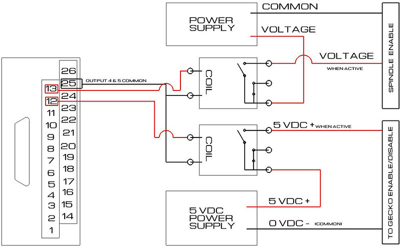
CSMIO IP-M Relay Diagram by mmoe5150, on Flickr
« Last Edit: July 28, 2014, 07:17:29 PM by mmoe »

Offline MXJ

*
  •  19 19
    • View Profile
Re: outputs 4 and 5 on CSMIO
« Reply #24 on: July 29, 2014, 03:54:54 AM »
Guys

Thank you very much for all the relies, I will work through them

Regards

Max
Re: outputs 4 and 5 on CSMIO
« Reply #25 on: July 31, 2014, 09:36:56 AM »

Offline mmoe

*
  •  23 23
    • View Profile
Re: outputs 4 and 5 on CSMIO
« Reply #26 on: July 31, 2014, 03:12:03 PM »
CSMIO/IP-M and VFD
http://www.cs-lab.eu/en/index.php?m=article&show&aid=132&uinfo=CSMIOIPM__VFD

BR
CS-Lab Team

In the link above, I believe you need to look at your wiring diagram and make a correction. Everything in the write-up is excellent, but I believe the diagram for wiring the relay is incorrect. From the write up:

Quote
If we at this moment enter the "M3" into the MDI line and we press ENTER the no. 1 relay will close the electrical circuit between the screw terminals no. 12 and 25. On the other hand in the „PlugIn Control\CSMIO_IP plugin\Digital IO” tab and „Diganostics (Alt-7)” tab we will notice active diodes of  „Output 1” (Mach3 virtual output) and „Digital outputs no.4” (digital output that controls the relay no. 1).

However, if you send a signal on no 12 to the relay as you show it, it will do nothing and remain open because a relay is operated by the coil, not the contacts at the switch side of the relay. The coil in your diagram is connected to nothing, so the relay will do nothing. Please review and compare to the diagram I supplied above showing how to connect the coils of the relays to the controller, rather than the switch outputs of the relays, which should be used to turn the intended hardware on or off using either the normally open and/or normally closed terminals of the relay. If the coil does not become active, the state of the relay (NC/NO) does not change.
Re: outputs 4 and 5 on CSMIO
« Reply #27 on: July 31, 2014, 04:01:22 PM »
Dear mmoe,

Remember that CSMIO/IP-M has got two relays inside and their coils are controlled by digital outputs no. 4 and 5.
Your opinion would be true if we were talking about CSMIO/IP-S or CSMIO/IP-A. Tomorrow we will place a basic scheme that should make it all clear 

Nevertheless, we really appreciate all your opinions, we read them carefully and analyze. Thanks  :)

CS-Lab

Offline MXJ

*
  •  19 19
    • View Profile
Re: outputs 4 and 5 on CSMIO
« Reply #28 on: August 02, 2014, 02:48:30 AM »
Output 4 is working properly!

Thank you all, and especially the team at CS labs

Cheers

Max
Re: outputs 4 and 5 on CSMIO
« Reply #29 on: August 06, 2014, 07:11:44 AM »
No problem :)

On a point of clarification - the new scheme was added:

http://www.cs-lab.eu/en/artykul-133-CSMIOIPM__VFD_Page_2.html#IPMandVFD

CS-Lab Team