The pics below show some details of my router.

X axis drive:

Y axis drive:

Z axis drive:

Typical limit switch and e-stop:

The spindle (not installed yet) is a TecknoMotor:

Plate used to connect the braided shields of all the limit switches:

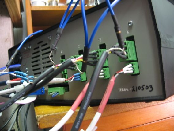
The controller is from PROMiCA (Australian company). It includes the axis driver cards, power supply, and limit and e-stop functionality:


Suprisingly, it did not include any grounding/earthing point so I made some. The posts just loop to the earth pin on the incoming power supply fitting:
In the bottom two pictures, I do not have my limit switches or the e-stop button connected. The bottom most green socket has two small loops of wire installed - the blue jumper is just a "dummy" limit switch circuit; the grey is the jumper for the e-stop.
When the stepper motors are energised and not grounded, I measure around 0.75V AC between stepper body and ground for the Y axis; 1.25V for the Z axis; 0V for the X axis. This makes me wonder whether there is an insulation breakdown on the Y and Z motors.
I can get my controller to "limit switch" trip when I ground a motor during running, so highly suspect some grounding issue.
The odd thing is when I ground all the stepper motors, limit switches and e-stop switch the controller is constantly tripped so I can't do anything.
There is a few more things I can do, like disassemble the two leaky motors to have a look see - but would appreciate help.
