Hello Guest it is March 28, 2024, 07:41:27 AM

Author Topic: Limit Switches and Interference  (Read 15697 times)

0 Members and 1 Guest are viewing this topic.

Re: Limit Switches and Interference
« Reply #10 on: October 27, 2012, 09:33:54 AM »
IMHO you have a grounding problem.

You never have mentioned who's breakout board, drivers, and power supply you are using.
 
Are all of those components properly grounded?
"It is well that war is so terrible -- lest we should grow too fond of it." Gen. R.E. Lee CSA

The United States Constitution (c) 1791. All Rights Reserved.

Offline Fastest1

*
  •  920 920
  • Houston, TX
    • View Profile
Re: Limit Switches and Interference
« Reply #11 on: October 27, 2012, 11:25:05 AM »
It is most likely a noise issue. Do you have a star ground? Is your Ve- from your power supply landed there? You need the shields, VE- and the earth ground to all be tied to a central point. I didnt have that one wire (VE- from my PS) tied into mine for years and tried every remedy to no avail. Just random triggers well into a succesful running code. Finally, due to my misunderstanding of electronics and what people were telling me all along, I connected that wire (praying to not release the magic smoke, burn or shock me). It worked! I now run 0 debounce and have not experienced a trigger since. I have even disconnected my shields and run stepper and limit wiring side by side as a test with no problems. Btw all shields are reconnected and wiring seperated as that was only a test, no need to be stupid. I do that plenty.
I want to die in my sleep like my grandfather, not like the passengers in the car! :-)
Re: Limit Switches and Interference
« Reply #12 on: October 27, 2012, 10:14:24 PM »
Grounding may well be the issue.  I've got lots to learn in this area, and having let the magic smoke out of one or two things in the past has me cautious  :-[

I'll post a few pics of my router on the next few posts - seems I can only post 4 pics at a time and getting some odd naming convention error at the moment trying to do it.

The frame is made out of aluminium extrusions bolted together with aluminium cast brackets or pieces of angle.  The frame is not grounded.

The stepper motors are mounted to pieces of aluminium angle.
____________________
Ian B
Re: Limit Switches and Interference
« Reply #13 on: October 27, 2012, 11:48:20 PM »
Here's a general pic of the router.

Hmmm.  Seems I can post one pic at a time provided it's small enough.
« Last Edit: October 27, 2012, 11:50:43 PM by brw0513 »
____________________
Ian B
Re: Limit Switches and Interference
« Reply #14 on: October 28, 2012, 12:09:22 AM »
The pics below show some details of my router.


X axis drive:


Y axis drive:


Z axis drive:


Typical limit switch and e-stop:


The spindle (not installed yet) is a TecknoMotor:


Plate used to connect the braided shields of all the limit switches:


The controller is from PROMiCA (Australian company).  It includes the axis driver cards, power supply, and limit and e-stop functionality:


Suprisingly, it did not include any grounding/earthing point so I made some.  The posts just loop to the earth pin on the incoming power supply fitting:
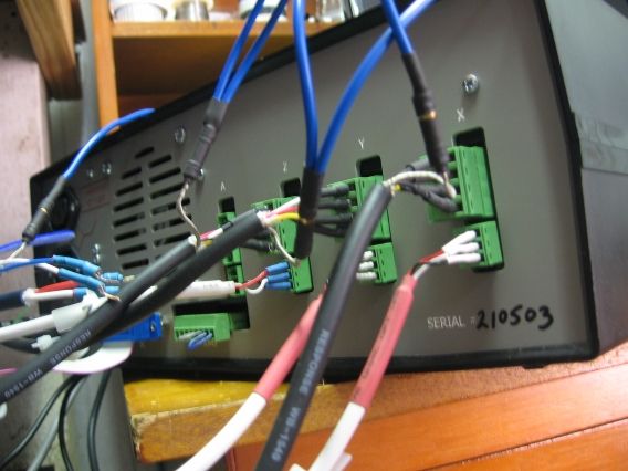

In the bottom two pictures, I do not have my limit switches or the e-stop button connected.  The bottom most green socket has two small loops of wire installed - the blue jumper is just a "dummy" limit switch circuit; the grey is the jumper for the e-stop.

When the stepper motors are energised and not grounded, I measure around 0.75V AC between stepper body and ground for the Y axis; 1.25V for the Z axis; 0V for the X axis.  This makes me wonder whether there is an insulation breakdown on the Y and Z motors.

I can get my controller to "limit switch" trip when I ground a motor during running, so highly suspect some grounding issue.

The odd thing is when I ground all the stepper motors, limit switches and e-stop switch the controller is constantly tripped so I can't do anything.

There is a few more things I can do, like disassemble the two leaky motors to have a look see - but would appreciate help.  
 
« Last Edit: October 28, 2012, 12:20:58 AM by brw0513 »
____________________
Ian B
Re: Limit Switches and Interference
« Reply #15 on: October 28, 2012, 07:05:13 AM »
After another hour or so of trials and tribulations, I think I've found a potential solution (pun intended :) ) although what I've found to work still seems a bit odd.

My stepper motors are wired with 4 core insulated (braided shield) cables.  At the motor end, the braid is not connected to the stepper motor body.  At the controller end, the braid is exposed and twisted together and soldered within a female bullet connector.  My intention was to use a mating male bullet for ease of connection of a fly lead to an earthing point.  I now wonder if the "proper" thing to do was to expose the braid of the stepper cable at the motor end and connect it to the stepper motor body?  But anyway..................   

When the stepper motors are energised, the un-grounded braided shield around each 4 core supply cable shows a small AC voltage.  Between the stepper cable braid and ground:

The Z axis gives 2.25V
The Y axis 2.0V
The X axis 1.75V

If I don't ground the stepper motor bodies, then each develops 1.5V AC between its body and ground.

When I leave these stepper braid sheilds ungrounded, but ground the body of the stepper motor and the braided shield of the limit switch cable runs, then the router operates perfectly.

Alternatively, if I ground the stepper motor braided shields and stepper bodies, but do not ground the limit switch cables, then the router operates perfectly too.

It is only when I connect the braided shields of the stepper motor cables and the braided shields of the limit switch cables that the controller trips out - and it happens instantly.  The PROMiCA controller is just not happy when I earth both the stepper cable braids and the limits switch braids.

Happy to receive any further comments.

     
____________________
Ian B

Offline Tweakie.CNC

*
  • *
  •  9,196 9,196
  • Super Kitty
    • View Profile
Re: Limit Switches and Interference
« Reply #16 on: October 28, 2012, 07:31:09 AM »
Just in general...

The shields of all cables are connected to GND at the controller end only and preferably to one single point or tag.
The machine frame and any other metal parts that you can touch are connected to protective Earth.
Earth and GND should be treated as two entirely separate circuits as far as wiring is concerned.
It is essential that you have no 'Earth loops' or 'GND loops' anywhere within your wiring.

The PC usually has its negative rail (GND) connected to Earth so this should be the only place where they meet.

Often points of conflict exist if the shielding of the LPT parallel cable or PC casing is connected to machine frame (Earth) or the heat-sink of a VFD is connected to the machine frame and also has it's own Earth wiring but there are many other areas where loops can easily be created.

As you have discovered, it is a difficult problem to resolve but unless it is resolved 100% then it may come back to bite you, at some future date - usually 3/4 of the way through a complicated and expensive job.

Tweakie.
PEACE

Offline RICH

*
  • *
  •  7,427 7,427
    • View Profile
Re: Limit Switches and Interference
« Reply #17 on: October 28, 2012, 07:56:13 AM »
You should not have 1.5V from the frame. From what your posting you don't have the spindle / router running. The source for EMI would be the router, router used a in an actual router being used for the spindle. Yes there will be EMI from the stepper cable leads at the motor but don't think the EMI field would create the 1.5V you are talking about.


RICH
Re: Limit Switches and Interference
« Reply #18 on: November 20, 2012, 06:37:32 AM »
I am pleased to say I have a solution to my limit switch problem :)  Not really the way I was hoping to solve it, but trying to find the source of the false tripping turned into a 2 week saga that was doing my head in.

I'm now using a 12V DC SPDT relay.  The six limit switches are in the 12V power circuit to the relay coil and the normally open switch is connected to the limit input to the PROMiCA IC3A controller.  It works wonderfully :) but I do have a 12V power supply and circuit that I never thought I'd need. 
____________________
Ian B

Offline Hood

*
  •  25,835 25,835
  • Carnoustie, Scotland
    • View Profile
Re: Limit Switches and Interference
« Reply #19 on: November 20, 2012, 07:03:40 AM »
This is the reason reason nearly all industrial machines run 24v for the signalling side of things ;)
Hood