Hello Guest it is March 28, 2024, 06:44:29 PM

Author Topic: Changing stepping driver / controller  (Read 7142 times)

0 Members and 1 Guest are viewing this topic.

Changing stepping driver / controller
« on: August 21, 2014, 10:34:13 PM »
Hi all
Not sure if this is in the right section but here goes.
I purchased a 2nd hand tabletop 3axis engraver/milling machine about 12 months ago and have finally managed to get it working sort of anyway.
However it has no provision for home stop switches just X,Y,Z and spindle control. The controller/ driver is housed in a blue box with a spindle speed control knob on the front. (cheap chinese model)
I have purchased a TB6600 stepper driver off ebay as I wanted to have home stop switches and be able to control the spindle through software.
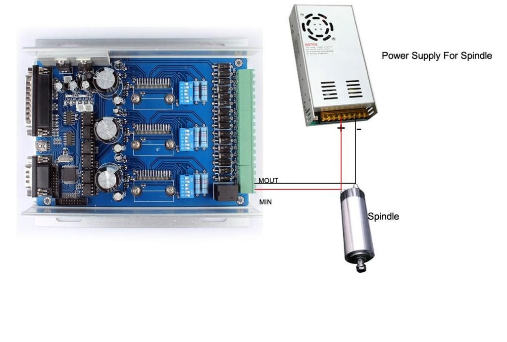
Unfortunatly I'm confused about the wiring for the spindle as to me it does not make sense. Looking at the wiring diagram the power goes straight from the power supply to the spindle and then on to the controller. To me that would mean that the spindle would be running at full speed all the time and not really controlled by the controller.
Here's the wiring diagram.
[/URL]][/img]

And this is the controller
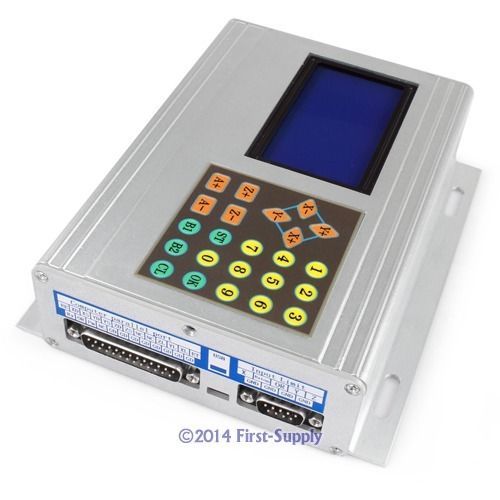
[/URL][/img]
« Last Edit: August 21, 2014, 10:36:27 PM by swampus »

Offline Tweakie.CNC

*
  • *
  •  9,196 9,196
  • Super Kitty
    • View Profile
Re: Changing stepping driver / controller
« Reply #1 on: August 22, 2014, 02:11:08 AM »
Isin't that just typical of the Chinese instruction manuals  ;D  ;D

The negative (-) should go from the PSU straight to the spindle (-).
The positive (+) should go from the PSU to the M in terminal on the controller.
The M out terminal on the controller should go to the spindle (+).

(M in and M out are just the relay contact connections).

Tweakie.
PEACE
Re: Changing stepping driver / controller
« Reply #2 on: August 28, 2014, 08:12:47 AM »
Thank you for the reply, it's good to know that  my limited electric knowledge was right.
Going by the wiring diagrams I would need 2 power supplies, 1 for the controller and stepper motors and 1 for the spindle.
However I'm wondering if I could get away with using just 1. I have purchased a 24v 20amp power supply to try.
I'm not 100% sure what the stepper motors are but I think they are nema 23. The code on them is 57BYGH56-4017B

Thanks.
Scott

Offline Tweakie.CNC

*
  • *
  •  9,196 9,196
  • Super Kitty
    • View Profile
Re: Changing stepping driver / controller
« Reply #3 on: August 28, 2014, 08:56:35 AM »
Hi Scott,

Try it by all means but I think you will find that you need 2 power supplies to ensure reliable operation of your machine. If the hole spacings of your steppers are 47mm x 47mm then you have NEMA 23's.

Just one point - you really need to find out the maximum current rating of your unknown steppers in order that this can be set (dip switches 4,5,6) within your controller. One guy (on another forum) has just found out the hard way http://openbuilds.com/threads/electronic-nightmares.630/#post-6597

Tweakie.
PEACE
Re: Changing stepping driver / controller
« Reply #4 on: August 28, 2014, 09:13:03 AM »
Thanks,
I wish I had seen that post before buying this new system. I take it if I set the dip switches to the lowest current and work my way up that should be safer.
As for the stepper motors I have not been able to find the exact same product code information but a product code that is close 57BYGH56-401A  which lists them at 2.8 amp.

Offline Tweakie.CNC

*
  • *
  •  9,196 9,196
  • Super Kitty
    • View Profile
Re: Changing stepping driver / controller
« Reply #5 on: August 28, 2014, 11:19:05 AM »
I think you would be wise to start at say 1.2Amps then see if they get hot after 1/2 hour's running. If they are still cool to the touch then move up to the next setting etc. - at least that's what I would do.  ;)

Tweakie.
PEACE