Hello Guest it is March 28, 2024, 12:00:06 PM

Author Topic: Has anyone actually got a C11 to control a KB speed control via Mach?  (Read 17557 times)

0 Members and 1 Guest are viewing this topic.

Re: Has anyone actually got a C11 to control a KB speed control via Mach?
« Reply #10 on: July 05, 2012, 01:46:30 PM »
I just found this datasheet on a (now discintinued) KB Electronic Potentiometer that I suppose performs a similar chore as the C11 only with pushbuttons to do the up/down speed commands instead of Mach inputs.  To ye of the Society of Magic Smoke Tamers it probably means something but to me not so much.  It connects to the F+ & F- terminals as well but I thought they were field connections for wound field motors, not PM motors as I'm using.

http://www.a-aelectric.com/pdfs/KBEP240d.pdf
Milton from Tennessee ya'll.
Re: Has anyone actually got a C11 to control a KB speed control via Mach?
« Reply #11 on: July 05, 2012, 01:54:53 PM »
Geez, can this be simply a case of "Should'a RTFM?"  From the KBIC manual:

"The output of the control is a linear function of potentiometer rotation. The KBIC®
can also be operated in a voltage following mode by supplying an isolated analog signal (0-7 VDC) to the
input terminals P2 (+) and F-. If an isolated input signal is not available, the optional Barrier Terminal
Board Signal Isolator (SI-5) can be used."


So, this means I should adjust the C11 on-board trim pot to 7V, connect the Gnd and 0-10V terminals to the P2 and F- terminals on the KB and Robert is my father's brother?
Milton from Tennessee ya'll.

Offline Vogavt

*
  •  260 260
    • View Profile
Re: Has anyone actually got a C11 to control a KB speed control via Mach?
« Reply #12 on: July 06, 2012, 08:25:01 AM »
Dickeybird,
In a moment of frustration on getting this to work, a couple of weeks ago I connected to the F+ and F- to my KBLC-19m. Huge flash! Huge!

Don't do this. It's reported elsewhere that at least on one of these board there's some faulty information.

It blew one of the traces completely off the KBLC-19M board. I resoldered it with a small shielded wire, then connected it to the A+ and A-. When I applied the power to the KBLC-19M with it back to "normal", it blew yet another set of traces!

This board is seriously hosed up and only good for parts (maybe).

Luckily, I'd bought two KBLC-19M's at the same time. I wasn't planning on having it as a spare; I wanted it for setting up my lathe.

Make sure you know what you're doing. Get some help.

In my case, I needed help..... professional help, because I dumped my cauldron of magic smoke! ;D

« Last Edit: July 06, 2012, 08:26:36 AM by Vogavt »
Re: Has anyone actually got a C11 to control a KB speed control via Mach?
« Reply #13 on: July 06, 2012, 08:58:11 AM »
Normally, two wires from the KB supply +12 v and 0 v to the ends of the pot track; and the slider picks up a variable voltage between 0 and 12 v depending on its position.  What the KB needs is a voltage at something between 0 and +12 v relative to its own 0 v supply, which is what the C11 supplies.  The problem is that the 0v in the KB may be waggling around relative to the ground of the C11 which is tied to "mains" ground, by up to +/- 250 volts, because of the way the KB controller works (I think).

So the question I would ask is whether your separate 12 volt supply shares an earth (or common) connection with the C11?  Assuming that it's connected to the appropriate pins on the C11, it may be that its -ve ouput is connected to mains earth which will also be connected to the common connection of the 5v supply.  I think that to work correctly the 12 volt supply may need to be completely isolated from the other supplies.  In my reading of the manual it is very vague on all of this.

Re: Has anyone actually got a C11 to control a KB speed control via Mach?
« Reply #14 on: July 06, 2012, 09:23:06 AM »
Hi John, I'm using a separate 12V power supply all by itself to supply the C11 speed control power input.  That part should be fine....unless I need to plug it in at the neighbor's house to completely isolate it. ;)

The paragraph from the KB manual quoted above is the answer...I think.  I would've verified it last night but after an evening of lawn mowing in 100 deg. heat and the appropriate celebratory libation, I was in no mood to joust with magic smoke. ;D

I've had the C11 gnd/0-10V outputs connected to the KB P1 & P2 terminals all along which must be wrong as the KB manual clearly states that it wants to see a 0-7V input at P2 and F-  I think what I'll do as a test is to connect a separate 3V source to those 2 terminals and see if I get roughly half-speed at the motor.

Thanks for the heads-up Vogavt, I definitely won't connect to the F+ terminal! :o  I'll post my results...good or bad.
Milton from Tennessee ya'll.

Offline Vogavt

*
  •  260 260
    • View Profile
Re: Has anyone actually got a C11 to control a KB speed control via Mach?
« Reply #15 on: July 06, 2012, 09:35:13 AM »
My 12V supply is independent for supplying voltage to the analog input of the c11 board.  Still no joy.
Has anyone actually got a C11 to control a KB speed control via Mach?
« Reply #16 on: July 06, 2012, 01:24:34 PM »
I have my c11 and KBMM-125 using the spindle control just fine. I can pull it apart tonight to see how I wired it up. I do know that I am using a separate dc supply just for the spindle.
Re: Has anyone actually got a C11 to control a KB speed control via Mach?
« Reply #17 on: July 06, 2012, 02:19:46 PM »
Thanks, that'd be awesome!  It'll really help Vogavt and I a lot. ;D
Milton from Tennessee ya'll.

Offline Vogavt

*
  •  260 260
    • View Profile
Re: Has anyone actually got a C11 to control a KB speed control via Mach?
« Reply #18 on: July 06, 2012, 04:40:35 PM »
Absolutely!

And for others benefit a simple schematic would be nice too! Not an electronics type schematic, but a wire from point A to Point B.

Okay, I'll admit it... it's really to help the voodoo electro-magical challenged like me.
Re: Has anyone actually got a C11 to control a KB speed control via Mach?
« Reply #19 on: July 07, 2012, 04:03:45 PM »
Well, I'm not electrician and it has been a while since I set this up but I will try to help.

Here is the C11.  The spindle control is on the bottom right.  The black and yellow cables just run to a DB9 port on the box.


The black and red wires from the C11 (for spindle power) run to a jack for this separate wall plug. 


You'll notice the power supply is actually 18V.  I know that the KB manual states the supply should be 0 to 10 or something like that but my motor is 110V and when I first set this up, I could not get it to power the motor up to full speed.  I spoke with Arturo from CNC4PC and he had me measure the voltage across the KB board with the PWM installed and it came out to more like 15V and in order to get 15V out of those leads, I had to use an 18V supply because there is a slight voltage drop.   

Here is a shot of the KB board.  The control wires from the C11 are the green/black wires in the heat shrink.  They are connected to the F- and P2 leads on the KB.


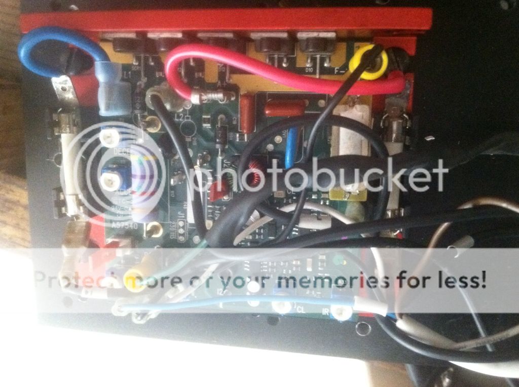
Now, I don't have my motor wired directly to the KB.  I have a g0704 and the original box had a FORWARD/REVERSE switch in place so I just left it (even though I don't use reverse).  I believe if you wanted, you could just run the A+/A- directly to the motor.  My A+ and A- go into the switch and from there it feeds back out to the motor (2 and 6 in this photo):


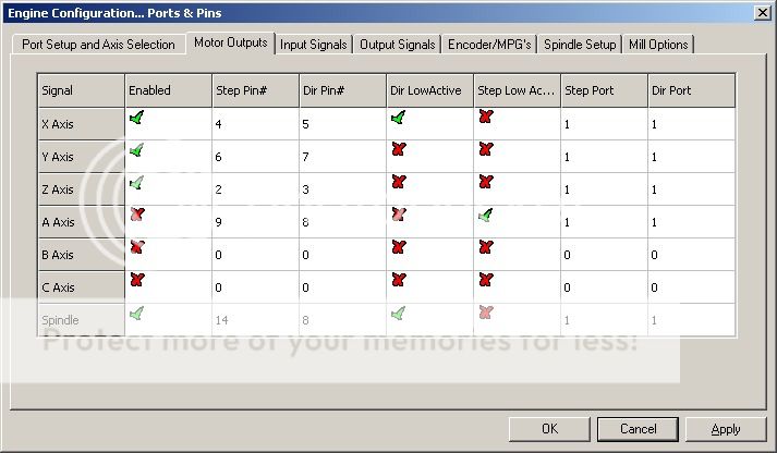
After that it was just a matter of setting it up in ports and pins: