Well, I'm not electrician and it has been a while since I set this up but I will try to help.
Here is the C11. The spindle control is on the bottom right. The black and yellow cables just run to a DB9 port on the box.

The black and red wires from the C11 (for spindle power) run to a jack for this separate wall plug.

You'll notice the power supply is actually 18V. I know that the KB manual states the supply should be 0 to 10 or something like that but my motor is 110V and when I first set this up, I could not get it to power the motor up to full speed. I spoke with Arturo from CNC4PC and he had me measure the voltage across the KB board with the PWM installed and it came out to more like 15V and in order to get 15V out of those leads, I had to use an 18V supply because there is a slight voltage drop.
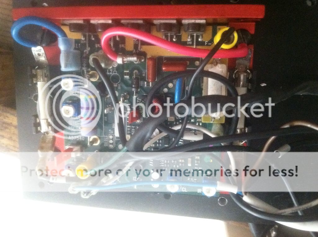
Here is a shot of the KB board. The control wires from the C11 are the green/black wires in the heat shrink. They are connected to the F- and P2 leads on the KB.

Now, I don't have my motor wired directly to the KB. I have a g0704 and the original box had a FORWARD/REVERSE switch in place so I just left it (even though I don't use reverse). I
believe if you wanted, you could just run the A+/A- directly to the motor. My A+ and A- go into the switch and from there it feeds back out to the motor (2 and 6 in this photo):

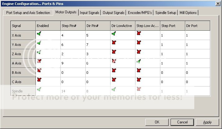
After that it was just a matter of setting it up in ports and pins:
