Thanks for that macro, although I must download something to view them properly as I'm using notepad and its all in a single string - not easy to read at all (as you can tell, haven't even thought about macro's until 4 days ago).
I'm all electrically hooked up now except for my stepper driver which was deemed 'out of stock' this afternoon

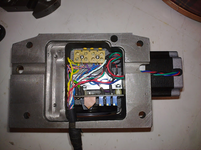
This is what my new cable looks like inside : (i have used 20 core video cable and tripled the wires for the stepper - its nice and flexible and screened too)
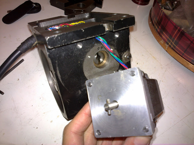
An aluminium adapter plate was made a tad less than 1/4" thick. The spindle of the stepping motor is 6mm and locates in the hole of the worm wheel shaft which seems to be smaller than 1/4" by a tad (drill blank wouldn't go in). A 3/32 hole was made through the motor spindle 1/8" from the end and a cross pin pressed in. This locates in the slot in the end of the worm wheel shaft. This pin has to be fairly accurately drilled.
This board operates on 12v, so three 12to5v DC-DC converters were used to step down the output signal voltage to a high of 5.1v and a low of 0.8v when measured with a multimeter. These outputs were then connected to pins 11, 12 & 13 on the C11G and mach reads them without a problem.

All i need to do know is get my head around Macros and make an efficient program. Tis all good fun

