The lathe was running well but i had a few accidents with the bed stops whereby when jogging off the limit switch i pushed the wrong button (home!!) after a software reset and homed again into the deadstop!.. crunch... it Damaged my 'Z' ballscrew, so i stripped it off to take a look. Now here is the old emco ballscrew, not really impressed I could bend it with my hands easy, but hey it’s only a litte training machine so you can pass on the plastic nut bracket i guess. There is nothing wrong with an 8mm (5/16) ballscrew but at 508mm long it is definitely a little too flexible.
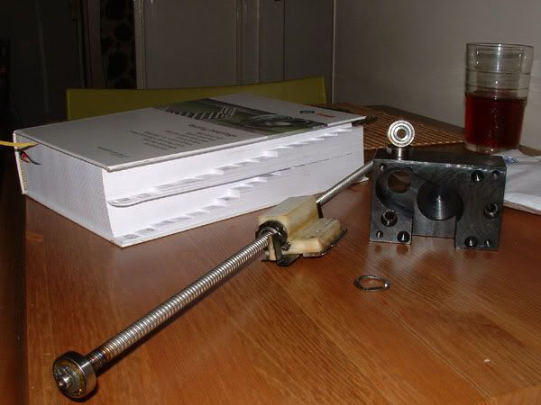
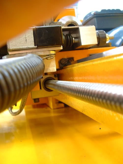
so i decided to make a steel ballscrew nut bracket, and fit a new ballscrew, the space under the carriage is so tight! i found the design a little testing to fit in a good device to hold the nut in firm without using to difficult a technique and still leaving room for the new screw guard / cover to fit over the top of it. I came up with a two piece nut which was blocked up on the mill, squared up on the grinder, then screwcut.
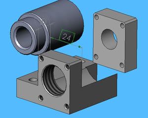
I wanted to have a firm hold of the ballscrew nut but not too firm that would distort its precision by clamping. The idea is you simply screw the ballnut into the nut clamp and then bolt on the other half of the bracket so it nips it in place and stops it unscrewing, the clamping dimension is just minus, so it literally may compress it by 1-5 microns. 23,993 - 23,998 as the ballnut is 23,999. I ground that size on the grinder after leaving some meat on the fitting face.
i decided to go for a 12mm diameter with a 4mm lead, a 16 x 5 I couldn’t make it fit in the constricting space. A 12 x 5 ballscrew would have fitted also but because of the greater lead it would increase the helix angle and reduce the torque transferred, although it would have increased my rapid speed. So, a 12 x 5 ballscrew gave me a helix angle of 7.62 degrees, a 12 x 4 comes in at 6.09 degrees. The original thread of 8 x 2.5 gives 5.71 degrees helix. 12 x 4 was a pretty good compromise, and I calculated if I just put that in, I should increase my rapid speeds to 1.8m/min from the existing 1.25m/min max.
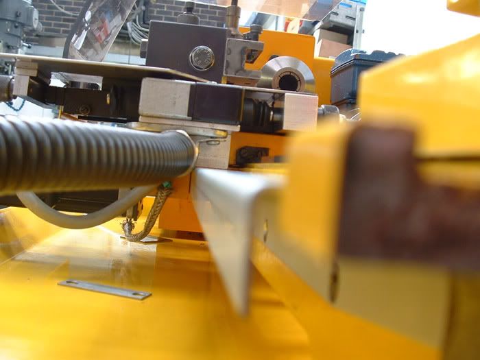
I had to space the ballscrew off on the X plane by 1.5mm away from the bed casting so the square portion of the ball nut bracket cleared the guard (since it was larger diameter!). to do this I retained the original brackets and modified them. I basically got some 1/16th gauge plate and made a spacer for the front supporting nut, and for the motor holding bracket at the back I elongated the original fixing holes by 1.7mm.
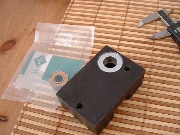
The existing ballscrew used two tiny ball single row radial bearings to support the rear of the ballscrew on a 6mm diameter (yes 6mm!).. so out the window that went and in the new ballscrew design I made that diameter 10mm and searched for a suitable bearing. I found a nice double row radial with some angular contact ability which could cope with increased forces radially and also increased thrust forces in both axial directions. Although not quite an angular contact thrust bearing it would be a much better replacement than the original single row radials. To mount the bearing again the space was tight but I managed to figure in the 26mm bearing o.d into the original rear mount bracket by boring it out to 25.99 (0.01 for the manufacturer recommended preload! To reduce the axial play to within 10-15 microns) so I bored it out and a tiny bit deeper and made a clamping washer like the original, pressed it in, put the washer over the top applied a holding force to it and peened the edges of the mount block over the bearing using a punch, its just to retain the bearing from moving axially that’s all. Once peened I licked it over on the grinder to remove the high spots.

I made a few hardened thrust spacers for the ballscrew, one for In front of the double row bearing and one for behind it. The one infront sits up against the ballscrew thread form and provides a contact point between it and the ballbearing inner and the spacer behind the bearing provides contact between the bearing inner race again and the timing pulley which actually drives the ballscrew, so nip up the drive pulley and it loads the ballscrew against the bearing, then it was locked off with a fine pitch grub screw. I also increased the threaded diameter on the new ballscrew, and had to re-thread the timing pulley with a new fine pitched thread etc. I had to relieve the bacl end of the bed casting a little to clear the hardened thrust spacer diameter, good old grinder came out to play.
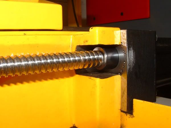
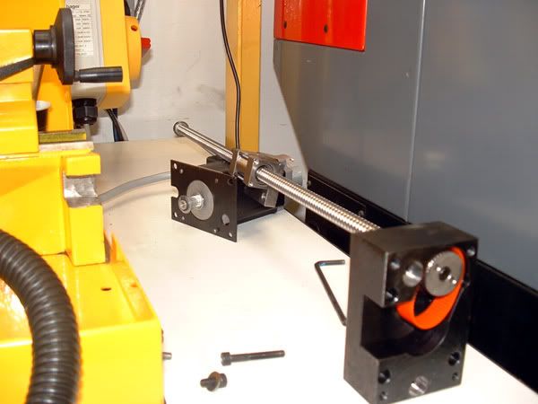
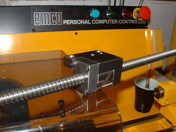
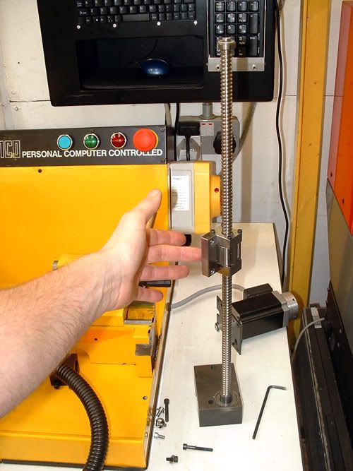
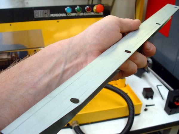
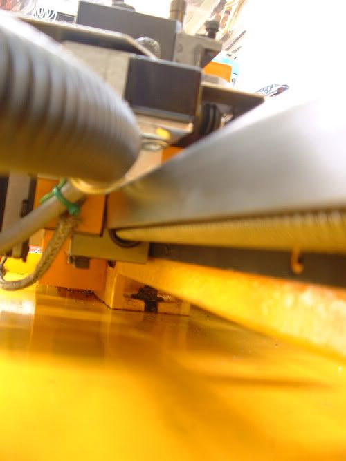
Everything fits as planned, and today I fitted up my new guard over the assembly, its so close if I paint the guard the paint will probably scratch off when the machine traverses, so I’m just going to leave it as it is.
The ballscrew bracket is one of two, the other is going to another retrofitted pc5 in holland. the ballscrew itself was precision rolled to c3 tolerance to the size I wanted. I checked it and I now have an error of 0.02mm over 250mm and an axial play (backlash you might say) of less than ten microns 0.01, this error (running clearence!) is from the double row radial bearing (the ballscrew itself is preloaded), if I increased the loading to maybe 15 microns on the major bearing diameter I would have reduced this axial play, but the manufacturer rec’d 0.01 so I just did what I was told!. It’s worked out well for me really I’m happy with those dimensional results, also Instead of a predicted 1.8m/min and probably because of the brand new screw it runs upto 2.1m/min easy!, I guess it has a good friction co-ef right now. I cant run it any faster because I am only using 2.2nm motors @ 49Vdc and they stall out over that speed, really.. 2m/min is well fast enough for this wee machine! I will only ever make tiny parts on it.
click here for a movie....
http://www.youtube.com/watch?v=1uW3F-qbZNkThe next job for me is to build a small remote pendant box type thing so I can use it properly, it is labour-some using keys to jog set tools and job.
