Thread milling Remember this for a 4th/5th axis turn center not a simple CNC lathe
For large diam threads Thread milling beats single point cutting hands down. Manual TURN machines and simple CNC lathes did single point because they had no other choice. Your machine has a choice as it is NOT a conventional LATHE.
A single operation.
IF your machine can MILL an accurate circle you can do accurate thread milling. Does not have to be as rigid as you think
I have a 20TPI threadmill that I use for large holes in aluminum, where no tap is available.
Cutter not any more expensive than a carbide boring bar with thread insert.
Can reach just as deep on large holes. Can even use the single point boring bar to do single point thread milling.
Absolutely, however, I rarely snap off a boring bar. In terms of spinning a single point tool, I do this to cut ACME internal threads above a certain diameter. I have a solid carbide single point ACME thread cutter that I mount in a boring head. For shallow threads, I might use the boring head to increase the 'diameter' of the cutter, and for larger stuff I would interpolate.
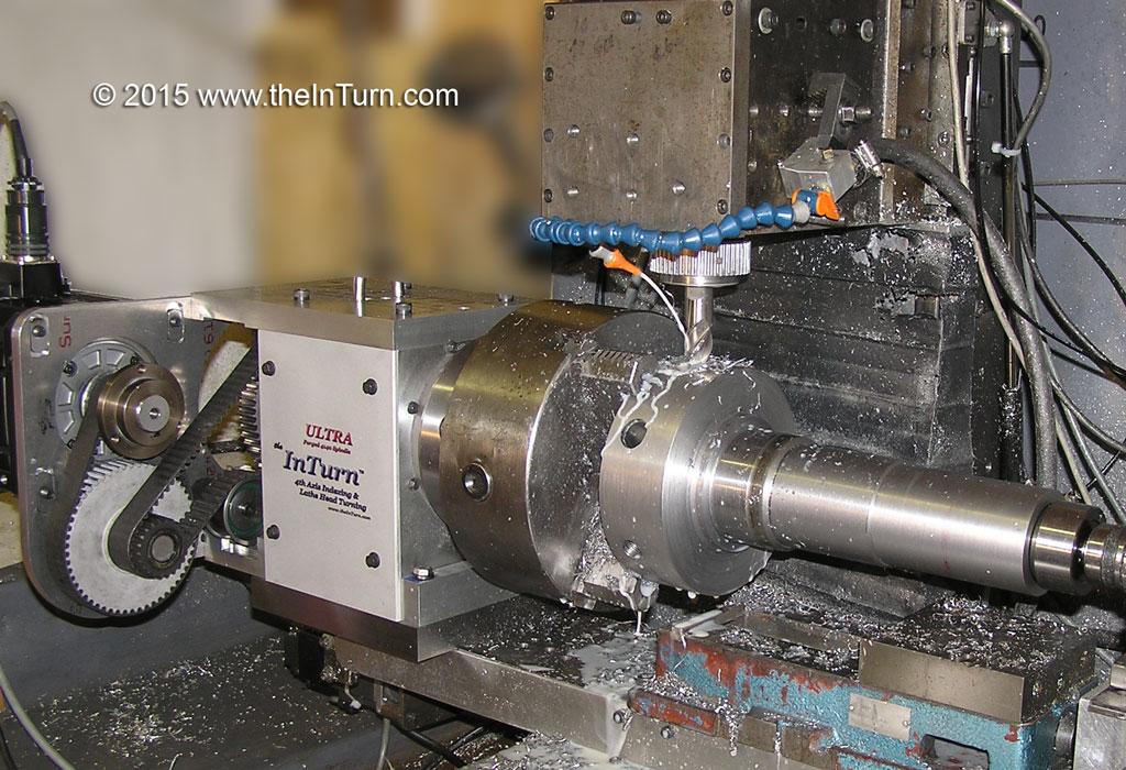
Overall however, I think we are talking about different things. I agree with you as far as using a thread mill on the mill spindle. The topic was cutting internal thread on a lathe (or the 'lathe' setup of a mill/turn specifically). For starters, you would need some way to spin a threadmill. I do have a horizontal spindle setup for the mill head, but as you might imagine from the photo, typically it would not be able to be positioned to reach into the end of a workpiece.
You are speaking in absolutes, and in that context I cannot disagree with anything you have said. However, another conversation is in the context of what is practical on a given actual machine, and those two conversations are different. Like discussing steppers and servos in as the same topic because they are both 'motors'.
As to operators responsibility. All standard threads and profiles are listed in the Machinist Handbook. All crusty machinists will have a copy(;-). No calculator needed but you WILL have to put your glasses on , at least I do.
Wow, you really ARE old school! Machinists handbook next to a machining center. That is an amusing juxtaposition. Sort of like having rails in front of a saloon to tie your car to so it doesn't wander off.

Creating the profile for the part to be threaded is normally a seperate operation as it requires different tools.
Before you begin the thread operation reguardless of what method the stock HAS to be the correct size. That way when the threads are cut to spec the profile is correct.
Well, a practical example is Collet drawtubes. I have to shave a tiny bit of the ID before threading. I use the single pint tool to do that <gasp. yeah, I said it! I don;t see any problem using the single point of a threading tool to shave small amounts to size the stock. Single point threading is the same operation. For those who get out of the shower to pee, this may seem like an abomination, but I just do it and not admit to it.

So, seriously, the pint is that with a 4th axis capable of turning and indexing (InTurn™ or higher end HMC) the tooling can be the same, -or- you can rig a number of tools. Realizing that your scope is to write a Wizard and not solve world hunger, I still can throw in as many fish as I can find and see what comes out of the pan, to use your analogy.
Here is a link to a private video (i.e. you will not be able to find it on YouTube without this link)
https://www.youtube.com/watch?v=wuzQhZnlBbANotice the multiple tools on the tool bar. In this case the hole is drilled for a tap, but it could just as easily be bored and single pointed. With Mill/Turn and gang tooling, you need to think outside the box.
As to clearance moves a good wizard will let you EDIT the GCODE on the FLY to add such moves. This one does as well {EDIT GCODE} OR I can add an edit Button that is conversational in nature BUT you still have to be able to tell it WHERE and HOW to dodge the problems. The wizard CANNOT read the part in the Chuck. (well it COULD but (;-))
Rememeber Wizards are conversational AIDS to programming NOT a robotic programmer of parts(;-).
Maybe you could just have a 'dodge' (I like that term) in X checkbox with a distance. That is really the only alternative when you run out of Z. The code would just as the X move out before the A rotation and then back in. These would occur in the same place as the unlock/lock commands. So basically
Unlock
--<is 'dodge' checked?>--
<yes> add G0X(distance var)
<no> no line added
Rotate A
--<is 'dodge' checked?>--
<yes> Add G0X(negative distance var)
<no> no line added
LOCK
-or-
universally add G0X(distance) where distance would default to 0 unless set by user
OK, enough chatter, here is a photo. You can download a higher res version here:
www.thecubestudio.com/pictures/UltraRadialDrillingSetup.jpg