Having finished installing the Mach3 drivers for the RNR Motion card, and tested every aspect of the card now, I thought I'd put in some notes for anyone thinking of this breakout card for Win10 conversion of their mill under Mach3.
This isn't a review. It's just what I learnt from using this card, which seems to offer a cheap alternative to the parallel port as a possible path up to Windows 10.
There are a few cards like this from different manufacturers. All seem to use the same driver for Mach3, and all seem to have similar pinouts. The driver is the RNR Eco Motion v2.0 driver. Some have a few differences, so perhaps there are different drivers also, but generally they seem to be the same from what I could tell. Most sellers seem to include a disk with a copy of the drivers, some chinese manuals and some english manuals, with say different things ( eg, configured completely differently ) however the english drivers and instructions do work.
The card looks like this.
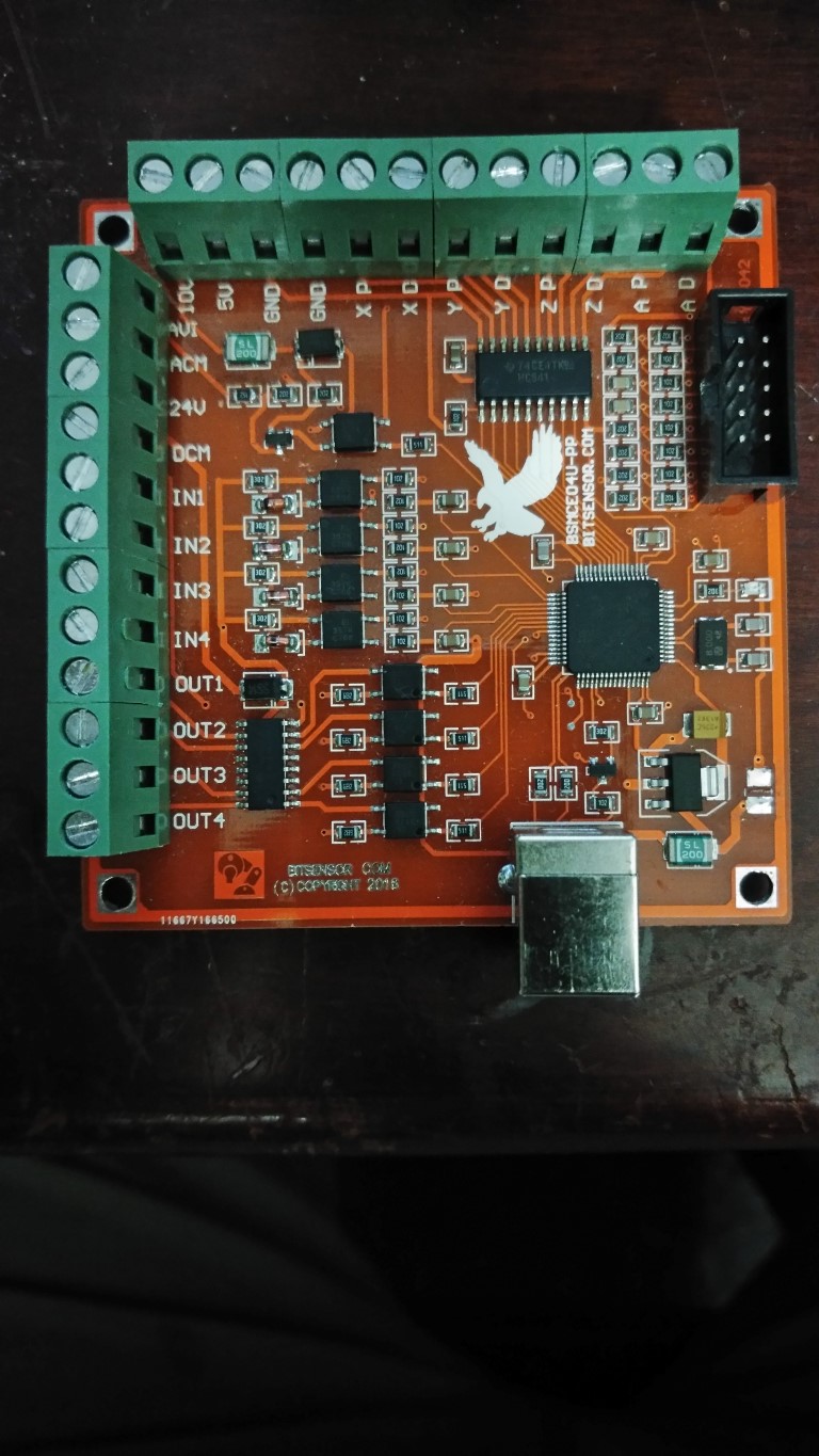
That picture shows a few missing components - mainly because I accidentally shorted it to 240vAC due to a faulty spindle driver... And attempted a failed repair, but a different version from a different supplier worked with the same driver and came with new drivers as well.
RNR Motion Cards use a 32F103 processor, which uses a USB interface to connect to the PC. It went straight in on mine, but others might need to adjust their USB settings under Win10. This wasn't a problem for me, but may require use of Zadig if you have Windows 10 attempt to use the wrong driver, which can happen if you use these chips and is easily and permanently fixed by manually selecting the correct USB Windows driver.
Note: The windows driver and the Mach3 driver are different. The windows driver should automatically work, but can be fixed quickly otherwise.
Once this is installed, copy the correct RNR Motion .DLL driver to the Mach3 plugins and Mach3 instantly recognizes it, and will put up driver card status updates onscreen - Which is probably normal, but I've found several chinese drivers in the past didn't even do this.
Plugin configuration looks like this;
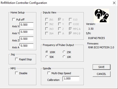
I don't know what Home Setup does yet, or "Rapid Stop" and I haven't tested "MPG-Disable" or Spindle Multi-step Speed or calibration. However the Inputs View does show which inputs are being selected whether they are configured in Mach3 or not, which is useful when troubleshooting.
The card drives 4 axis - and each axis is driven by a push-pull driver, so you can configure as positive or negative into the stepper controller. It's only 5v though, and there's just one 5v output and two ground outputs, so better to drive as positive current loop into the stepper controllers. There are outputs for Pulse and Direction for each axis.
The MPG input ( i mentioned the pinouts in my previous post ) are all 3.3v pulled-up inputs and the A and B inputs are 5v and require a 5v capable wheel. They are positive A and B inputs. Both will be "low" when on a detent, with each pulsing once per detent rotation. These are NOT buffered and care should be taken to avoid causing damage to the board when wiring these up. They will either be a 10 pin 0.1" pitch header which takes a standard polarized IDC 10way connector, or will be screw terminated.
There are four other inputs which can be set up, and are 24v pulled-up output and should be tied to ground to activate. External supply of 24v is required, though I also tried 5v and it worked just fine, though using the USB ground or 5v supply is not a good idea.
The 24v inputs also drive four outputs and these are mapped to four input pins on Port 3 - in fact all inputs are mapped to Port3 in the order they are displayed ( vertical before horizontal ) in the configuration panel for the controller. Even the A and B pins for the MPG, though these don't have to be set. ONLY the A and B pins don't need to be mapped. They are MPG1 by default. The rest must be manually mapped to whatever application you put them to. The labels are just "suggestions" and it's pretty much up to you what you do with them. If you don't want x10, for example, you could map it to e-stop.
Only the four 24v inputs are opto-isolated. The MPG inputs go straight to the main chip.
The outputs are also mapped directly from Port 3. So Port 3, pin 1 can be an input or an output, but the two operate independently. Setting the output low doesn't automatically make the input low as well. They are independent although they use a common ground that is independent from the stepper output ground.
The analog output is a 10v output, but in practice I found this changed up to around 9.3 volts depending on the wiring and load placed on it when attached to a brushless controller. There's about 5 or 6 config screens to get this going - they are shown in the english manual and the pictures are correct. Once installed, they can be used. They have a separate ground to the digital inputs and the stepper outputs yet again, and must be supplied 10v and Gnd from the controller. The output can then be fed back into the controller and works well enough. I tested it with a chinese XDJD WS55-220 Brushless spindle controller and the only problem I encountered was that the controller won't start if the voltage moves up slowly - such as in the auto-calibration test. I didn't use positional feedback for the motor - just output and open-loop control. When the voltage moves up slowly, the controller tries to start the motor, stalls and fails to start it at all. Then nothing happens. Sufficient voltage MUST be sent to the controller to start with - more than 1.5v. Otherwise it will fail everytime. Once Mach3 was configured to 1.5v minimum output, there was no further problem with the analog output running the brushless controller, though I think this was a controller fault and not the control board.
All of these boards seem to cost around $20 to $30 and came with a USB cable and a driver. They use an original USB cable too, in case you want a longer one, which you probably will.
I hope this helps anyone considering using one of these to get around the parallel port limitations in windows 10 to determine if this card meets their requirements. In my opinion, it's greatest weakness is that it only has four generic buffered inputs, and it's biggest strength is that it's cheap and works well, with drivers, manual and even english instructions supplied - or at least they should be.
David.
