Hello Guest it is March 28, 2024, 12:49:09 PM

Author Topic: BT30 spindle from scratch - with power drawbar and ATC of course  (Read 562398 times)

0 Members and 1 Guest are viewing this topic.

Offline simpson36

*
  •  1,369 1,369
    • View Profile
Re: BT30 spindle from scratch - with power drawbar and ATC of course
« Reply #540 on: September 25, 2013, 06:11:13 AM »
I think the challenge will be to find a planetary gear set that is compact enough and can handle that much power.

Speaking of power handling, it is encouraging to know that BT30 can handle the power that Chinon is pushing thru it. Doubling the power handling changes the landscape considerably. I would still like to find some hard engineering data on the capacities, but the Chinon specs are a good start and the drawbar tension chart you provided is priceless  . . especially considering the endless debates that took place on that topic a while ago. I run the BT30s at 1,000lbs  . . excuse me 1,000lb FORCE to keep the author happy . .  ::)   so I think that's in the ballpark.

Meanwhile, I have completed the new design for a BT40 spindle and located heavier springs (coil, not belleville) to meet the spec in your chart. I can see now where the bellevilles come into play. It looks as though I would not be able to go any larger than BT40 using an off-the shelf die spring.  Good to go with BT/CAT40 though so now I have a quandry as I have already started collecting BT30 tooling.

Its always something . . .  :'(
« Last Edit: September 25, 2013, 06:13:42 AM by simpson36 »

Offline Hood

*
  •  25,835 25,835
  • Carnoustie, Scotland
    • View Profile
Re: BT30 spindle from scratch - with power drawbar and ATC of course
« Reply #541 on: September 25, 2013, 05:51:56 PM »
Yes that is indeed the problem, I stripped an old van gearbox in the hope I would find some suitable gears but all were too big to fit in the space I have.

Regarding the max power handling capabilities of 30 taper, I would take a guess that the Chiron is close to but within the safety margin of the 30 taper, it is a German machine of very high quality meant for high production (not that I use it for that ;D ) and Germans dont just take guesses, they are anal about these kinds of things ;D
 I suppose there is a chance that  Chiron decided they did not need the max possible with a 30 taper but as said above with it being meant as a high production machine I would imagine they have made it close to the max.

The force gauge I made up was a good and a bad thing, good thing is I now know the force my drawbar exerts, bad thing is I think it is low and I have no information on my spindle so I am really in a quandry, do I try and find the way to strip down or do I just use as is and just hope for the best ;D


Hood

Offline simpson36

*
  •  1,369 1,369
    • View Profile
Re: BT30 spindle from scratch - with power drawbar and ATC of course
« Reply #542 on: September 26, 2013, 01:09:39 AM »
You did not say what your drawbar force measured out to be, but FWIW, in my early research on BT30 (I did not look at any other sizes at that time), what I unearthed was a dual spec for BT30 with significantly different tension specs above and below a certain RPM.

The tension specs were 600lbs and 1,000 lbs (above a certain RPM), but I don't recall the RPM break point. I *think* it was 6,000 RPM, so you might be OK as is.

In any case, one would imagine the drawbar having a threaded collar that bears against the spring pack . If so, then it would simply be a matter ot tightening that collar down a bit. Keep in mind that tightening a collar in this arrangement is also taking out travel, so it would be prudent to make sure (after such an adjustment) that the sping stack is not 'bottoming out' (binding) before the pull stud is completely released.

Offline Hood

*
  •  25,835 25,835
  • Carnoustie, Scotland
    • View Profile
Re: BT30 spindle from scratch - with power drawbar and ATC of course
« Reply #543 on: September 26, 2013, 04:41:25 AM »
I only have 400 lb-f . I do not have any specs on what it should be but I feel it should be higher.
See pic below, it shows almost 1200 PSI but I deliberately made my piston 1/3 inch square so that the value is trippled and thus the 1200PSI is actually only 400PSI.
The big problem I have is I do not have any drawings available to me to even see how things work. I do not even know if it uses bellevilles or some other means and I do not even know how to take the spindle out to see. In fact taking the spindle out itself will not even show me as everything seems to be internal in the spindle and dismantling that seems to be quite involved.
 I have found a few bits and pieces of info regarding spindles in Chirons but they are different models and from different years and all a bit different from one another so not even sure if they are of help.
  I know it is air operated as two pipes go to the front of the head casting but other than that I am in the dark. I am in Hopes that Graham Waterworth may manage to get me some info as he has asked a friend who is a CNC Tech and he in turn is going to ask around to see if anyone can tell me. Failing that I will just have to go in blind and hope I dont screw anything up, spindle rebuilds I think will be rather expensive ;D
 
Hood

Offline simpson36

*
  •  1,369 1,369
    • View Profile
Re: BT30 spindle from scratch - with power drawbar and ATC of course
« Reply #544 on: September 26, 2013, 11:07:00 AM »
I only have 400 lb-f . I do not have any specs on what it should be but I feel it should be higher.
See pic below, it shows almost 1200 PSI but I deliberately made my piston 1/3 inch square so that the value is trippled and thus the 1200PSI is actually only 400PSI.
Hood

I do not understand the math. 1/3" square piston is .11 SqIn.    


Offline Hood

*
  •  25,835 25,835
  • Carnoustie, Scotland
    • View Profile
Re: BT30 spindle from scratch - with power drawbar and ATC of course
« Reply #545 on: September 26, 2013, 11:24:40 AM »
Words were arse for tit, should have been square inch not inch square :)
I have just tested the gauge by removing the pullstud and taper section and passing the bar through a hole bored into a lump of steel, I then screwed in some threaded rod with a ring welded to the bottom. I suspended from the press's table and stood in the ring. Gauge showed approx 600 to 650 PSI (was awkward to view when standing on it and looking at it upside down ;)  ) I weigh 95  Kg so that is about right, 95 x 2.2 x 3 = 627Lbs so 627 PSI on gauge.
Hood

Offline BR549

*
  •  6,965 6,965
    • View Profile
Re: BT30 spindle from scratch - with power drawbar and ATC of course
« Reply #546 on: September 26, 2013, 07:58:23 PM »
Hood you have to be carefull not to take a big bite at a time You now have more Torque at a lower rpm. You may be on the edge of a 30 taper capacity to be able to hold the tool holder rigid. You will have a LOT more torque to take a bigger bite. Yes it still has the same KW but a very different torque band.

If your guage is correct and it appears to be, you are VERY LOW on pressure for the drawbar. We always used 1000psi for the no go on a 30 taper below that and heavy cuts could cause problems. Bet you have some broken spring washers in there. Best to fix it rather than worry about it "What IF".

Just a thought, (;-)TP
« Last Edit: September 26, 2013, 08:02:52 PM by BR549 »

Offline Hood

*
  •  25,835 25,835
  • Carnoustie, Scotland
    • View Profile
Re: BT30 spindle from scratch - with power drawbar and ATC of course
« Reply #547 on: September 27, 2013, 02:51:20 AM »
Terry, I tend not to take big cuts but I definitely would like to get the drawbar force up to where I think it should be. I am in hopes that I can get some info on how things are constructed and put together but if not then I suppose I will just have to pick a quiet spell and then get stuck in and hope I dont do more harm than good ;D

Hood

Offline simpson36

*
  •  1,369 1,369
    • View Profile
Re: BT30 spindle from scratch - with power drawbar and ATC of course
« Reply #548 on: September 27, 2013, 03:06:10 AM »
A scary possibility is that the gripper is unthreading itself from the end of the drawbar (assuming it is threaded on).

If that were the case, then it *might* be possible to screw the gripper back onto the drawbar using a conically shaped tool thru the spindle nose and into the gripper. A 'pinecone' shaped carbide burr with a long (6") shaft (as used in porting work on automotive engines) would do nicely. The gripper should be hardened (either finger or ball type) and if you turned the tool shaft with your fingers, no damage will occur and you might be able to feel whether the gripper was turning or not. Likely you would need to try with the drawbar set On and OFF and ideally somewhere in between if that is doable on your setup. Objective here is to assure that the gripper is not being used as a stop (or in some other way being forced against a surface internally) which would prevent it from turning.

In case you do find the gripper loose and are able to get it screwed back on, a 'Q'-tip saturated in GREEN locktite and touched to the end of the drawbar should get some of the stuff wicked up into the threads. I would place this stuff somewhere between blue and red in holding power.

In any case, good luck with the spindle. My bet would be that (if the spindle is a 'cartidge' arrangement) you can get to the drawbar and spring stack without disturbing the spindle bearings.

And you really don't want to disturb those guys. Here's why;

I have a precision option for the InTurn™ 4th axis now and my next mill spindle will have precision bearigns as well, so I have been spent a lot of time studying spindle designs, perusing white papers on vibration analysis and reading the precision bearing specs and handling proceedures as published by SKF, NTN, TIMKEN, and so on. Typically they say 'In the event you have to remove a bearing, it is best to replace it'.  ???  $300 - $400 bearing . . . times 2 . . .   JUST replace it?   Yikes!  :o

Oh yes . .  and . . . the replacement bearings are slightly smaller than the OEM, so the spindle will need to be 'reground to achieve the correct fit.'  Gee, suddenly the bearing cost seems almost trivial. . . :'(

How's this for a tollerance (EOM bearing supplier for Excello) Quote:  '  
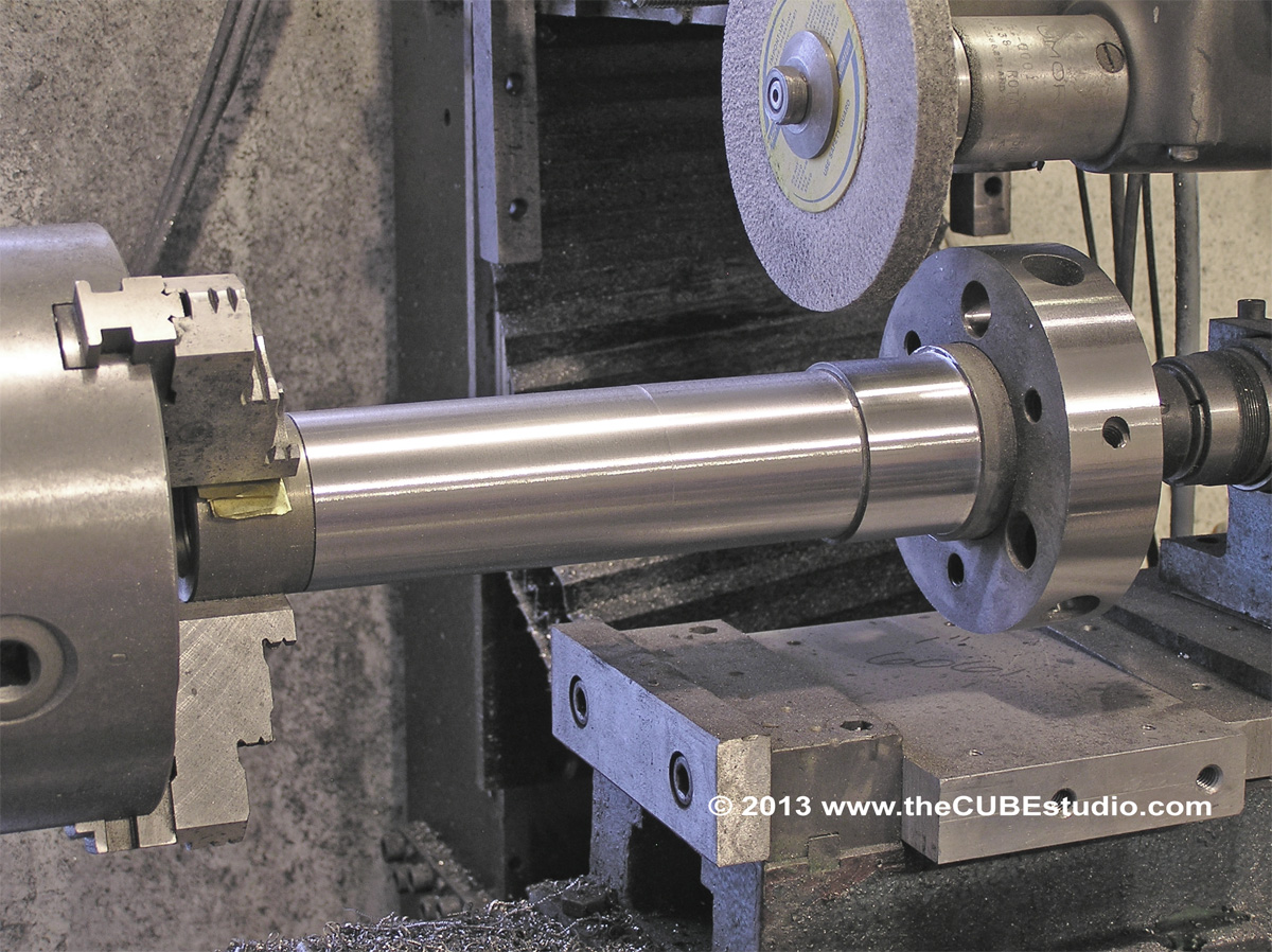
.0001" tight to .0001" loose '      . . . .  bizzarre.  Staying within two tenths is doable for me . . barely . .  but it takes a lot of time because I have to 'sneak up on it' as my machinist buddies used to say. Here is my special one-off hardened A series tool steel spindle. It is currently cut for a standard press fit to a ABEC3 deep grove ball, so there is meat on there to re-cut it for precision bearings. I just need to grab a couple while I'm out getting bread and milk . . . . .


Offline Hood

*
  •  25,835 25,835
  • Carnoustie, Scotland
    • View Profile
Re: BT30 spindle from scratch - with power drawbar and ATC of course
« Reply #549 on: September 27, 2013, 02:30:44 PM »
I really think it s more likely the springs are broken or weak as I do know they have never been replaced in at least the last 10 or so years.
Dont really want to have to dismantle bearings etc but I have found a PDF from McBroom Industrial Services that mentions removing bearings  before removing drawbar but whether it needs to be done in that order I wont know until I either strip it down or hopefully manage to get a part drawing. Also dont even know if my spindle is like the one in the PDF or not.

Hood