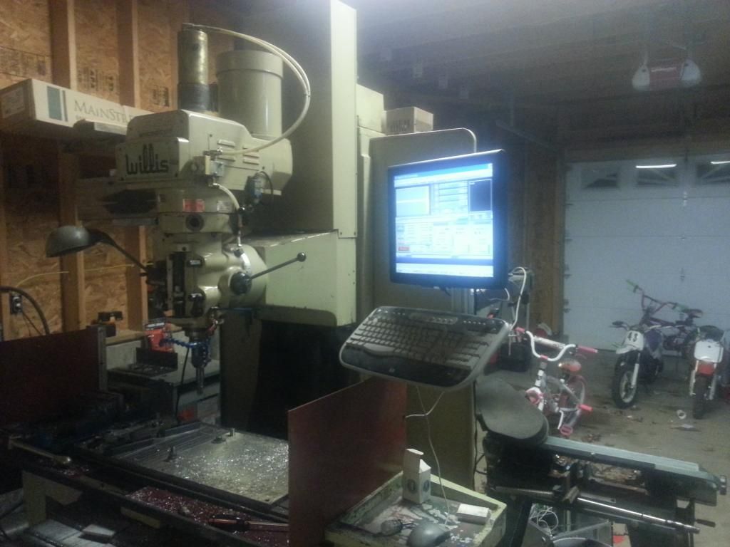
Time to start yanking wires! One last look at it....
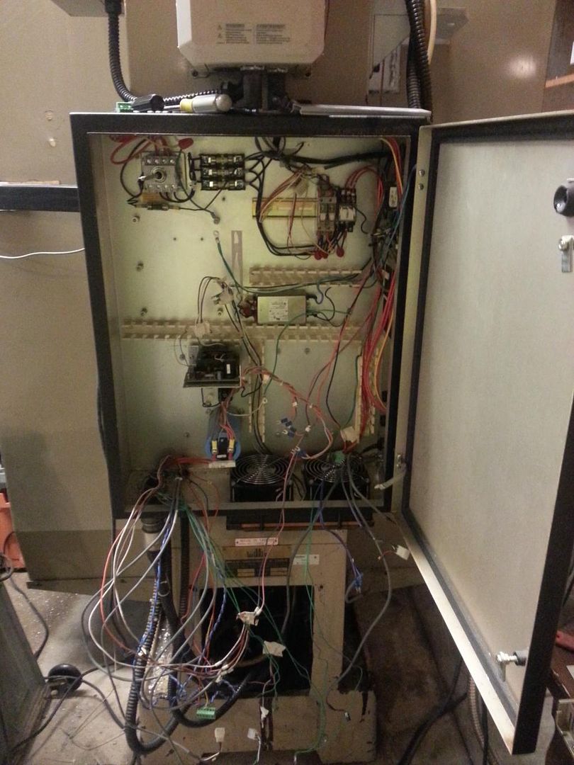
Mostly gutted...
I decided to mount the PC internally to try and keep things neater, wires shorter, etc. I came across a touch screen at work, picked it up for a whole $20.
So the thinking is the motors are good and I will use them. The existing power supply should power the motors just fine since they did with the original drives, right? The original power supply is just 120v rectified with a large cap so 170vdc. More on this later.
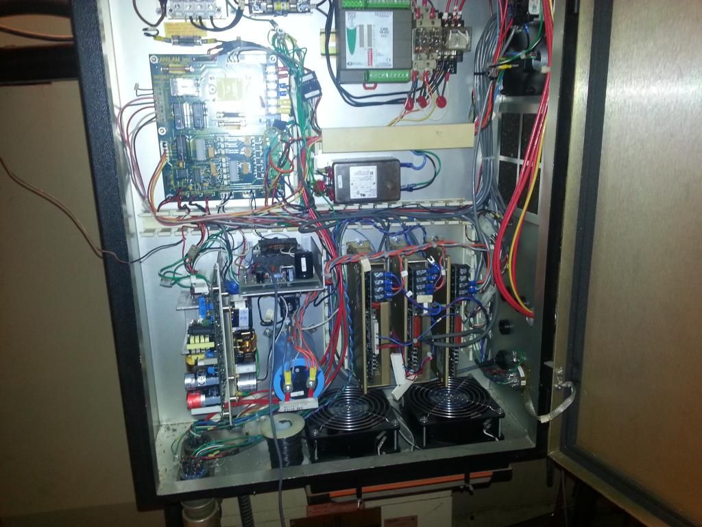
The drives are here, so time to get busy wiring. Lots and lots of wires, and lots of reading material. I had to fab some angle brackets to mount the drives card style. This kept them directly over the existing fans.
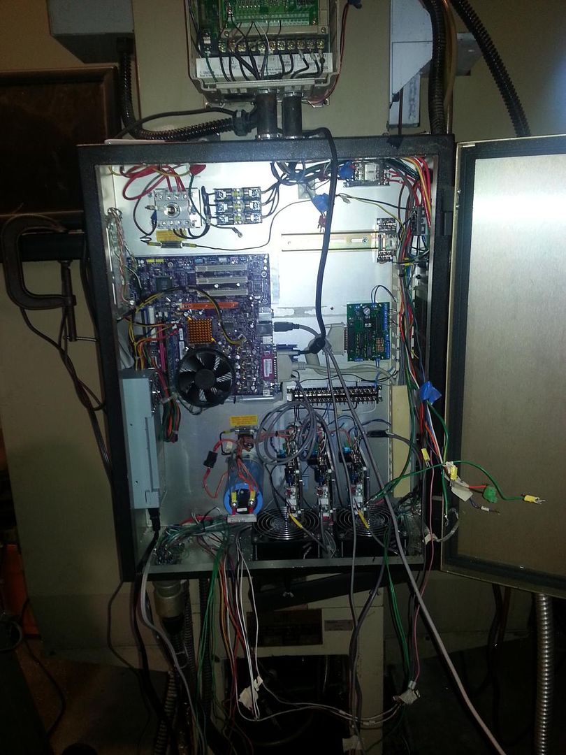
At this point I was able to power up the drives and make some initial moves. Servos were not tuned, but motion was still decent right out of the box. This was very basic at this point, no limits, no servo enable, but I had motion. I also ran into an issue. I could not (or rarely could) turn the drive power on without tripping a breaker. I even burnt out a contact on my power switch. The current draw was way too high at startup. If you look at the pic above I have a power resistor inline after the rectifier. This allowed me to turn it on, but limited me on performance.
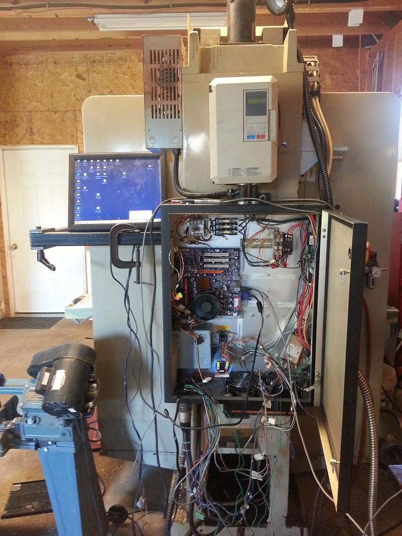
To fix this, I needed to add a relay that would pull the resistor out of the circuit after a delay. Well I need a servo enable relay, a relay to bypass the resistor, and a timer. At some point I planned on adding a PLC, because I plan on adding a toolchanger and who knows what else down the road. So PLC added, two relays for servo enable, and limit wiring tied to enable relay. The PLC is programmed to close the first relay then the second after a couple seconds. It is also tied to Mach via modbus, and locks out the reset button when servos are not enabled.
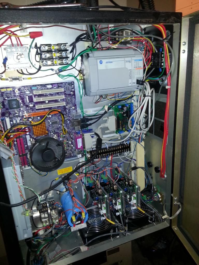
So at this point it is functional, though the interface leaves much to be desired. A simple touchscreen and keyboard will do for now, time to fabricate a real operator interface.