Hello Guest it is April 20, 2024, 01:05:01 AM

Author Topic: running unipolar stepper motor with TIP120  (Read 4231 times)

0 Members and 1 Guest are viewing this topic.

running unipolar stepper motor with TIP120
« on: June 25, 2010, 09:00:27 AM »
hey

there are two circuits using same transistor but one of them do not have diodes. i read bout these diodes as following:

The diodes are a feature typical of circuits that handle magnetic coils, that is inductive circuits. In this context, the motor windings are the inductive element. Capacitors provide a means for the storage of electrical charge, inductors provide a means for storage of electrical current. The driving current causes a magnetic field to be built up in the coil. As soon as the drive is removed, the magnetic field collapses and causes the inductor to release its stored current. Semiconductors are particularly sensitive to these currents (they briefly become conductors and then become permanent nonconductors!). The diodes provide a mechanism to safely shunt these currents away and, thus, protect the transistors and the computer.

but in second circuit there is not diodes. why. how much important to use these diodes. if not to use diodes then which are general measures to save transistors?

and there are some detail about earth wires:

You should also note that ground for the transistors must be made common between the parallel port (say at pin 25) and the motor power supply. An additional wire with an alligator clip can be used to provide access to the ground for the motor power supply. So, on the motor side of the circuit we have six wires, one for each coil, one for ground and one for the motor voltage on the shunt diodes. The motor (positive) voltage supply is provided through the common coils.

I am not clear about coil wires which has diodes and another alone wire. Please tell me in detail about these wires.
and also tell me about connection of motor with circuit which has not diodes.

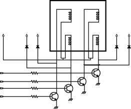


http://www.forth.org/fd/Step.html

Offline KTM

*
  •  92 92
    • View Profile
Re: running unipolar stepper motor with TIP120
« Reply #1 on: June 25, 2010, 10:05:26 AM »
The TIP122 has a built in diode - reverse biased for the back EMF
Re: running unipolar stepper motor with TIP120
« Reply #2 on: June 26, 2010, 12:30:03 AM »
hi

thanks for your reply. but how is more batter to use diodes? Please what mean by "reverse biased for the back EMF". And again i am asking about the measures to protect the transistors from being burnt as described in following sentence.


"The diodes are a feature typical of circuits that handle magnetic coils, that is inductive circuits. In this context, the motor windings are the inductive element. Capacitors provide a means for the storage of electrical charge, inductors provide a means for storage of electrical current. The driving current causes a magnetic field to be built up in the coil. As soon as the drive is removed, the magnetic field collapses and causes the inductor to release its stored current. Semiconductors are particularly sensitive to these currents (they briefly become conductors and then become permanent nonconductors!). The diodes provide a mechanism to safely shunt these currents away and, thus, protect the transistors and the computer."

how the motor coil's conman wire and the four diodes wires will be used.


Offline stirling

*
  • *
  •  2,188 2,188
  • UK
    • View Profile
    • www.razordance.co.uk
Re: running unipolar stepper motor with TIP120
« Reply #3 on: June 26, 2010, 04:09:35 AM »
but how is more batter to use diodes?
It's not better - it's neccessary - both your circuits use diodes but as KTM has already said - the TIP122 has them built in to the package. They're not shown on the diagram because that is just the schematic of a darlington pair.

how the motor coil's conman wire and the four diodes wires will be used.
The motor's common (centre tap) wire connects to your supply +ve as do your 4 diodes.