I was asked to check pins with LEDs.
Here are the results.
To explain what's going on with the board, I can select to ground the LEDs on one rail or supply +5 to the LEDs on the other rail.
The 8 LEDs represent the 8 output pins. X-axis is on the right side. Step pin is first, then Dir pin.
I have verified that the diagnostic board I made is functioning properly.
There is more to read after the images. First I added +5V to the LED array. This is the result.
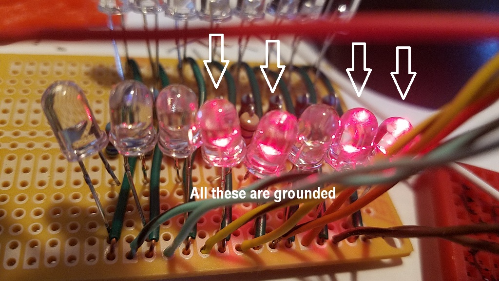
The lit LEDs are showing ground on the breakout board.
There was nothing else spectacular here.
Next I grounded the LEDs on the other array.
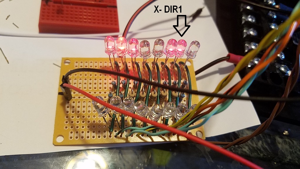
The X-Dir pin is lit and when I toggle the direction, it goes out
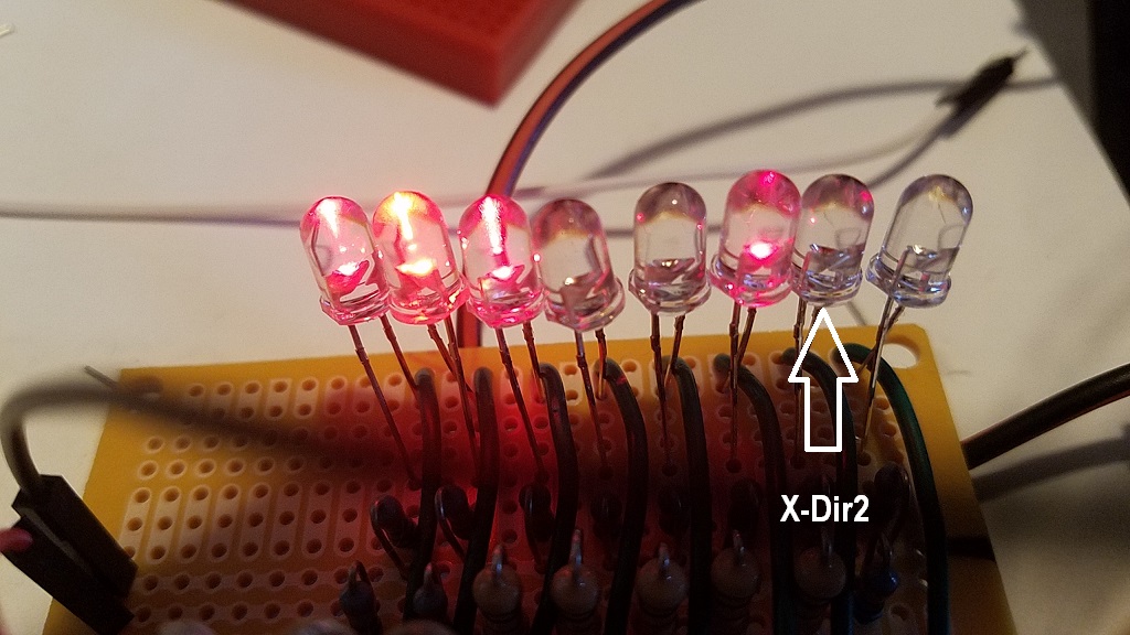
And when I engage the X step I can clearly see the X step LED working
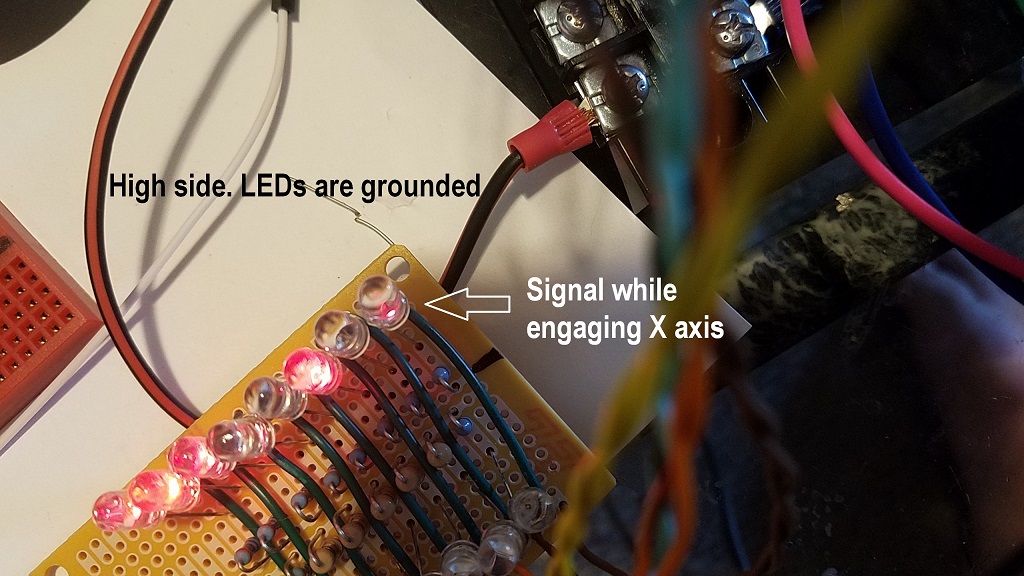 NOW the interesting part
Or maybe not so interesting, depending on how much you know about this stuff.
If I have power to the breakout board, and it's hooked up to the computer through the parallel cable, I get the outputs above.
If I disconnect the parallel cable, the board, essentially, goes dead as far as the output pins are concerned. There is neither +5 nor ground once the parallel cable is disconnected.
So, the LED test verified exactly what I saw in the motor test. Only the X axis is getting a signal. The step and Dir on the other 3 axis is not functioning, whether set high or low in the output pin settings.
So, is it a bad cable? Bad port driver? Bad breakout boards? Time will tell.