Hello Guest it is April 24, 2024, 05:08:09 AM

Show Posts

This section allows you to view all posts made by this member. Note that you can only see posts made in areas you currently have access to.


Topics - DICKEYBIRD

Pages: « 1 2 3 4 5 6 »
41
General Mach Discussion / Question for Dolphin CAD/CAM users
« on: March 24, 2013, 11:03:03 AM »
Just got Partmaster v10 lathe (Thanks Hood!) and for the life of me can't get my TurboCAD .dxf's to load into DCAM consistently.  It worked a time or 2 but now I get a page with tiny little gibberish at what looks like random spots.  If I zoom in on one I get a part of the drawing with "Light_6" and "Light_4" next to it.  That sounds like 3D stuff but it was drawn in 2D.  I've tried all 3 available .dxf file save options (R2000, R14 & R12) in TCAD with same results.  Sound familiar to anyone?

42
General Mach Discussion / CamBam & lathes?
« on: March 08, 2013, 06:52:52 PM »
Anybody on board actively using CamBam for lathe work?  I know most of you are big on Dolphin but I can't handle the price.

CamBam have a trial version but new software is so hard for my dumba$$ to learn and I don't want to invest a ton of time if it's useless.  Most of what I need to do is pretty easy stuff that I can handle with Mach wizards but I do need something that can handle internal elliptical or parabolic curves from .dxf's.

43
General Mach Discussion / M3/M4 spindle reverse safety?
« on: February 19, 2013, 11:16:22 AM »
I'm adding a spindle reverse relay to my lathe (3/4 hp Baldor DC motor w/KBIC-120 controller) equipped with CNC4PC C11 B.O.B. with the 2 relays.

Is there a way in Mach to prevent the system from trying to instantly switch directions if (when) I mistakenly enter an M4 right after an M3 (or vice versa) in MDI or in my code?  KB says "DON'T DOO DAT!"  I should've held out for a deal on one of their controls with the reversing module built-on but I didn't think I'd want spindle reversing at the time.

Obviously I'll do m'best to always put in an M5 and a pause to let the spindle stop before changing directions but I know myself too well to assume perfection. ::)

44
General Mach Discussion / Soft limits broke in Turn?
« on: February 09, 2013, 04:43:49 PM »
I have Homing working well on my ORAC now and was attempting (unsuccessfully) to set up soft limits today.

Searches show a range of posts from "soft limits don't work at all in Turn" to "X works but not Z" to "Z works but not X" to "it's on the list to be fixed" to "it works great."

I seem to have trouble setting up anything new so it may just be me but am I wasting my time trying to make it worK?

45
General Mach Discussion / W2000 & Mach?
« on: January 19, 2013, 12:12:04 PM »
I noticed the splash screen when Mach starts loading says "CNC Controller for Windows XP & 2000."  I just took an old Dell small case P4 900 with W2000 Pro out of service and was wondering if it'd run Mach well enough to control an old, slow MicroMill I have.  It has 80 in/oz steppers and goes maybe 12-15 IPM on a good day so speed isn't a big factor. ;)

The small form factor Dell box is just right to fit nicely in the available area.  Reckon 2000 would work OK or should I wipe it clean and throw XP on it?

46
Show"N"Tell ( Your Machines) / A project from a year ago
« on: December 20, 2012, 11:47:50 AM »
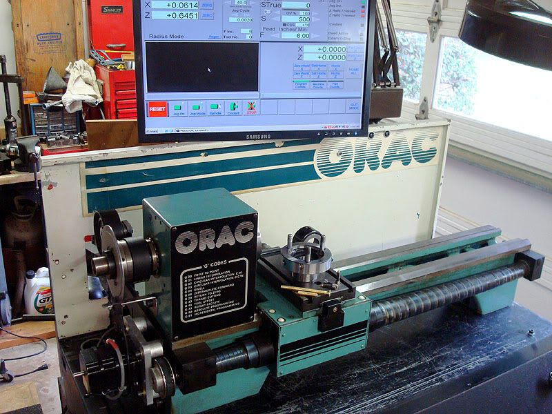
This project is over a year old but eventually made me a decent size lump of cash.  Here’s some info & pics that may be interesting to my fellow newbies.

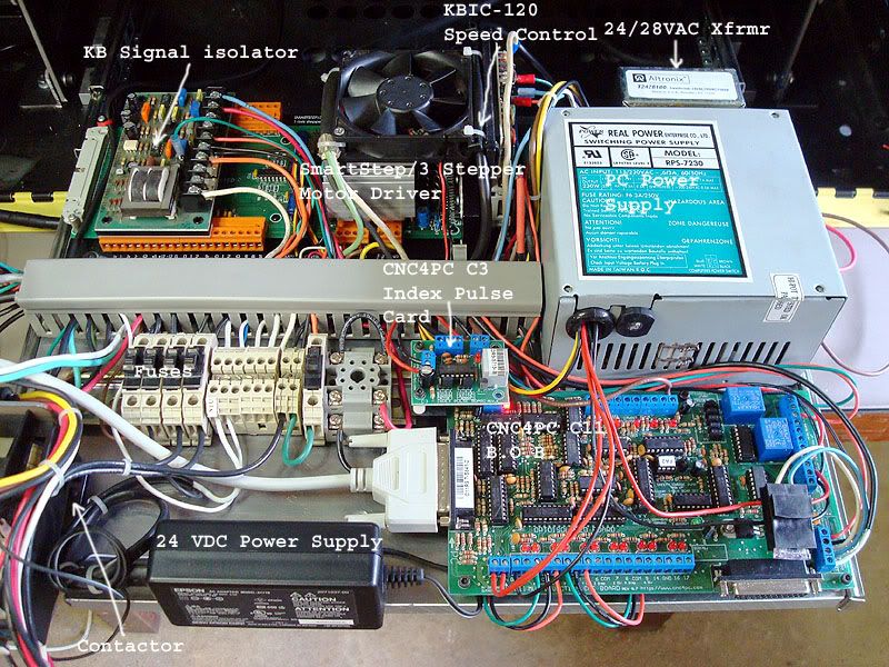
I bought a Denford MicroMill off Craigslist for $100 with no software or dongle.  With help from various nice guys on the Denford UK forum, I was able to remove the serial board from the SmartStep3 controller and connect the step/dir/gnd pins to a B.O.B. and control it with Mach.  Once I got the axes moving I went through the thing adding acetal thrust washers to tighten up the slop, gravity feed oilers and brackets to connect the top of the Z column to the enclosure to take out much of the flex in the column.  I also added a counterweight/pulley system to the Z to ease the burden on the puny (80 oz/in) stepper motor.


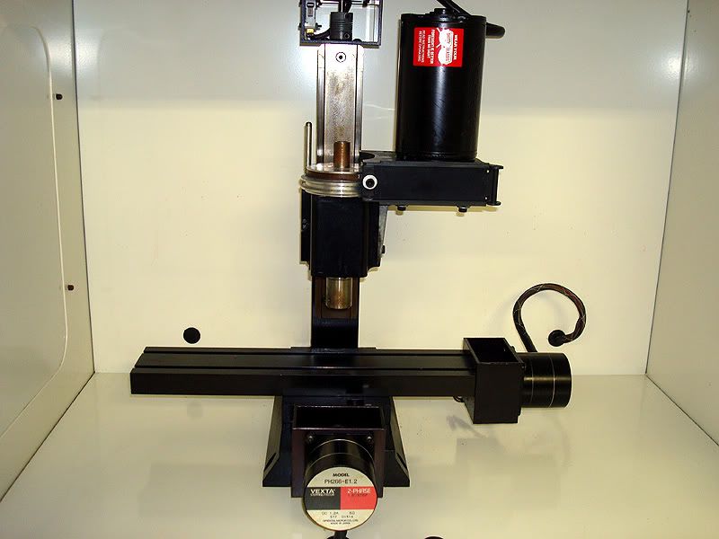
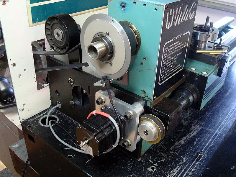
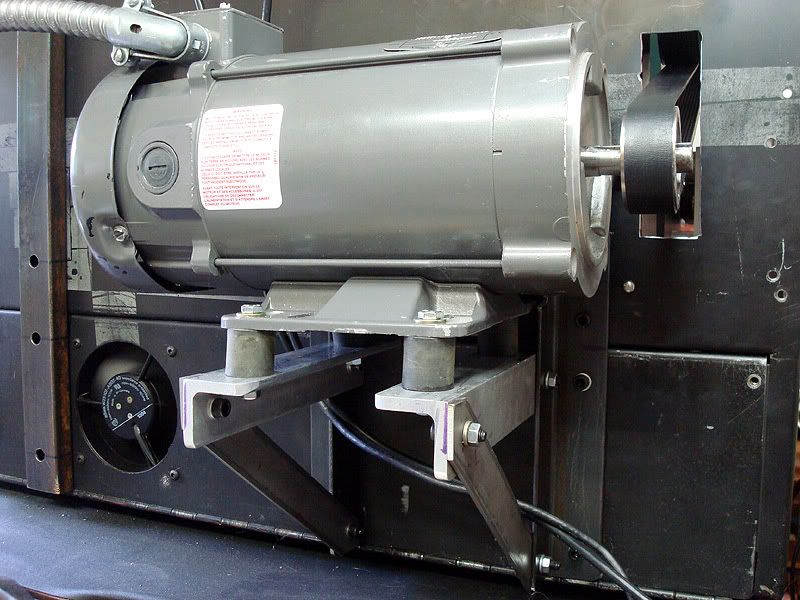
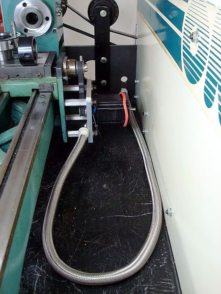
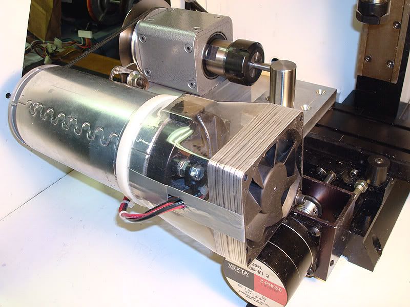
It worked as good as a tiny mill could but I decided what I really wanted was an option to add a CNC lathe function.  I had enough stuff lying around to cobble up a treadmill motor powered ER32 spindle assy. that mounts to the left side on the mill enclosure floor.  I added rectangular steel tubing bolted underneath the enclosure floor to stiffen it up before mounting the assy. and it’s plenty rigid for the small work I’ve done with it.  Hood just thinks he’s got a “wee lathe....THIS is a wee lathe!


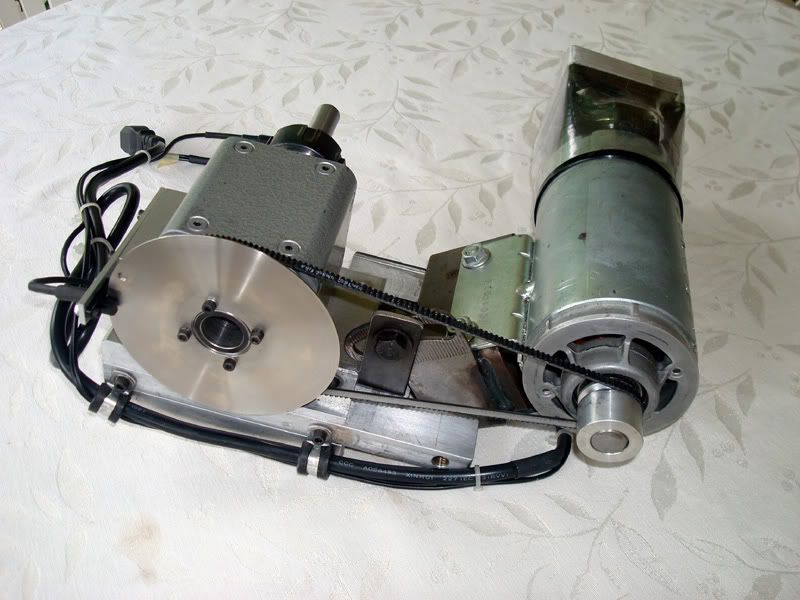
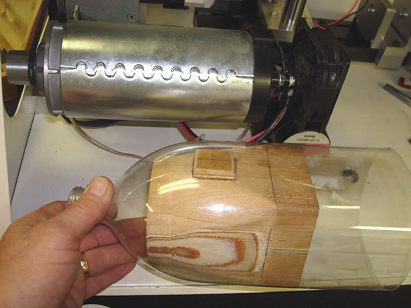
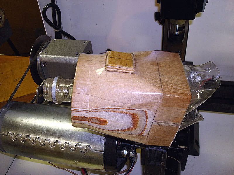
I had removed the treadmill motor’s flywheel/fan to install the drive pulley and was concerned about overheating so I installed a 12V server cooling fan.  I made a plastic duct by heatshrinking a 2 liter soda bottle (P.E.T. plastic) over a homemade wood plug.


I made a little toolpost and mounted it on the left end of the mill table and it worked very well for what it was.

Coincidentally within days of getting it running, a neighbor/friend down the street asked if I could repair some roller shafts for him and the company he works for. The shafts were manufactured by one of their vendors and are beautifully made from 303 stainless covered by a precision ground rubber cover. The problem was that that the shafts were snapping off at an e-clip groove after being in use for a while. The bottom corners of the groove weren’t made with the specified radii and the sharp corners created a stress riser and the shaft eventually fatigued & broke there. My task was to remachine the groove using a wider tool with larger radii in the corners to blend into the “floor” of the groove, taking a minimal amount off the diameter.


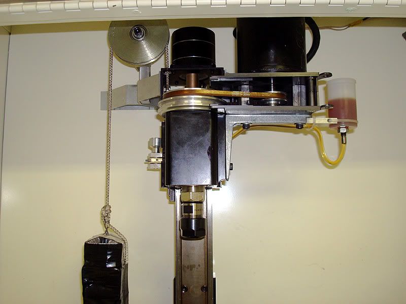
The shaft had to be chucked by an aluminum sprocket on one end and fortunately was small enough that I could make a thinwall acetal bushing and chuck it in a 3/4” ER collet.  The other end of the shaft had to be restrained by a tailstock.  Mine had no tailstock so I had to make one that bolted to the floor of the enclosure on the right side and straddled the mill table.


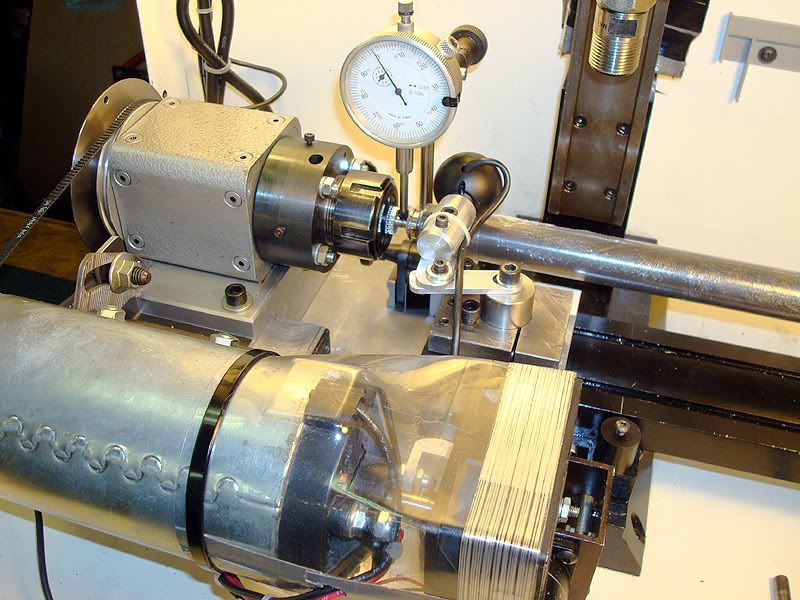
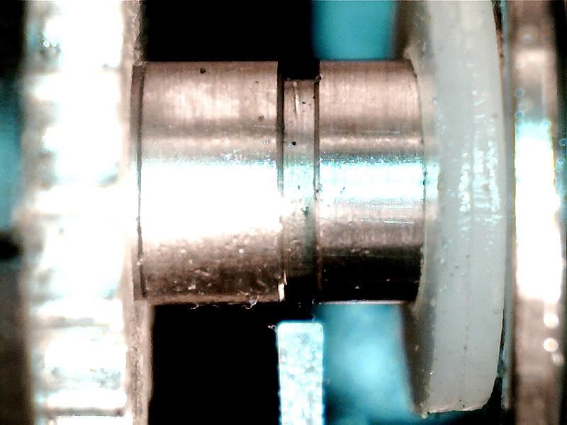
Once the shaft was chucked up, I realized I could barely see the groove much less the .0075” specified radii in the corners or the bottom of the groove.  I mounted a cheap USB microscope to the machine so I could see the groove & tool alignment and set the depth of cut properly.  Here’s the view through the scope.  To give a bit of reference, that shaft is ¼” dia. And the Kaiser thinbit carbide tool is .021” wide.


Unfortunately the close up view with the shaft turning revealed the groove wasn’t concentric with the shaft or the sprocket so I made a D.I. tip with a .015” blade to reach down into the groove to accurately measure the runout of the bottom of the groove.  The runout tests made me a bit queasy as I found it was different on every shaft and I realized every one of the 1060 shafts would have to be dialed in individually before making the cut!

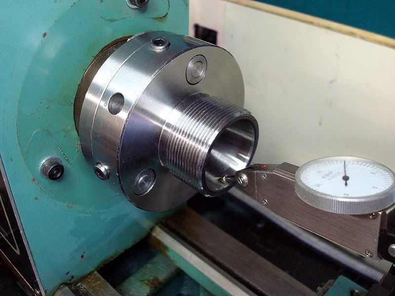
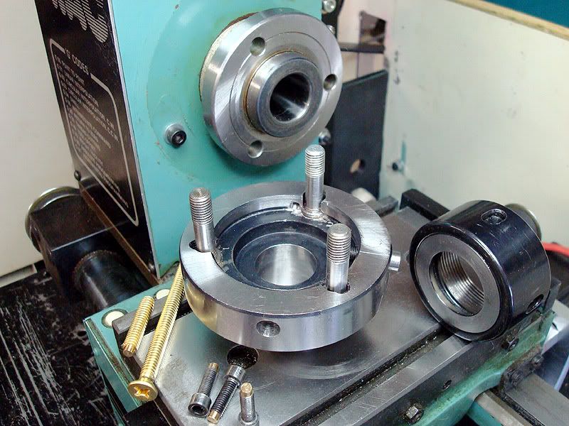
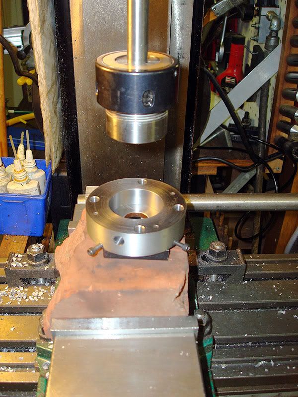
 I decided I would have to make an adjustable (poor man’s set-tru) ER32 chuck that would both do the job and fit into the tiny bit of real estate available in my little machine.  I wasn’t confident enough in my skills to make a new spindle from scratch so I sacrificed an ER32/R8 and a ER32/MT2 collet chuck to make it. I cut them apart and added 2 interference fit flanges with a raised boss on one and a recess in the other to allow the 4, 6-32 brass-tipped screws to adjust the shaft into place before the 4 nuts are tightened. I turned a press-fit sleeve to go onto the end of the R8 shaft so that I could single point the 1 1/8-18 TPI thread to fit the preload ring nut and turned & polished a 30 mm journal to fit the pulley end bearing. The R8 taper was turned down & polished to fit the other bearing.


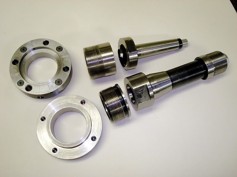
I used the mill to assemble the shaft and ER stub to the pre-heated flanges to insure proper alignment.  The .002” interference fit holds the parts together well.


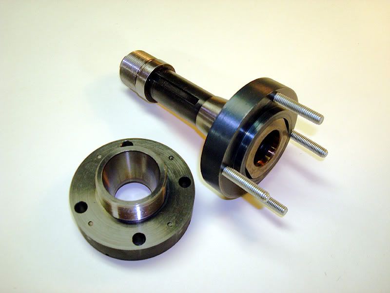
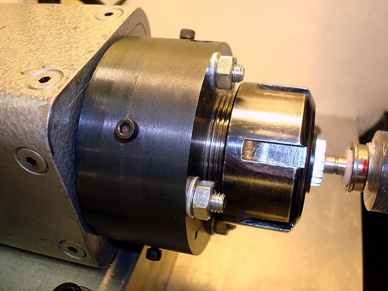
It worked great and allowed me to chuck up the shafts & dial in the groove bottoms to .0002” to .0005” runout even though some of them were slightly D-shaped.

Here’s a pic of the rig in use.  I became very familiar with this view over the 4 months of spare time it took me to modify the machine and finish all 1060 of the shafts.


47
General Mach Discussion / Safe version # for Turn?
« on: December 09, 2012, 05:05:45 PM »
What's the least buggy version of Mach 3 Turn?  Mine is R3.043.022

I've finally got my opto home switches up & working on the ORAC and want to get this thing into a solid configuration.  I'm pretty sure the weird things it's doing are due to my ignorance but I want to make sure I'm starting with as solid a version as possible as I go forward.  What version are you guys using that actually make parts consistently with your lathes?  I'm using a solid PC with a good PP (no external controller.)

48
General Mach Discussion / Mach 3 T-shirts??
« on: November 25, 2012, 09:11:48 AM »
The T-shirts from my last hobby are getting ratty.  Couple of searches for Mach shirts turned up nothing.

Has nobody ever made up any Mach T-shirts?  If not, it seems like easy money for the good folks at ArtSoft.  A logo with some kind of catchy statement would be easy for those artsy folks that do T-shirts in bulk.  Something like "Control the world of CNC with Mach 3" or whatever.  Then when Mach 4 catches on you have another opportunity.

49
General Mach Discussion / 3rd axis on a lathe?
« on: October 06, 2012, 09:43:35 AM »
I'm accumulating the nec. bits & pieces to add a small powered aux. spindle on my ORAC.  It'll be a while before it's done but was curious how to get the extra DRO window added to my screen.  Are there any screens already out there with an extra axis?  Will the tool path show up in the preview screen?

I figure if I start now, maybe I'll have a clue how to do it when I actually need it 2 or 3 mos. down the road.  I'm slow. ;D

50
Show"N"Tell ( Your Machines) / Denford ORAC lathe retrofit.
« on: August 21, 2012, 01:16:10 PM »
Been working on a Denford ORAC retrofit for much longer than I’m willing to admit but it’s getting close enough that I figured I’d stick m’toe in the water and join the fun.

I bought it from a fellow in Detroit and had it shipped by truck to me here in west Tennessee, USA.  I work for the local Jaguar-Land Rover dealer so am experienced with British engineering.:D

It was purchased with nothing other than the bare lathe and the stripped clean base unit.  I also have a Denford Micromill converted to Mach control and had bought a spare SmartStep/3 controller for it so that’s the controller I chose to use for the ORAC.  Meager budget & all y’know.

The ORAC base unit had no structure underneath the lathe other than the sheet metal top and I felt it would flex so I added some crosswise angle iron braces with vertical brackets to tie the top more rigidly to the bottom which has lengthwise stiff channels.  It all seems very rigid now.

I added a couple Home Depot drawer slides and a piece of aluminum plate to use as a pull-out equipment tray as I knew I’d be putzing around with electronics a lot and needed good access to it all.  The big aluminum plate serves as a dandy heat sink as well.  The original front panel was missing so I cobbled up one from a piece of heavy gauge metal shelving hinged with a piece of B727 access panel hinge that was given to me.

The missing original motor was ½ hp AC  w/VFD but I got a brand new ¾ hp Baldor DC motor off eBay cheap..  It was way too big to go in the original location and had to be mounted on the “back porch” and a hole cut in the back panel for the belt.  The KBIC-120 SCR speed control & motor made such a loud buzzing noise I had to mount the motor on rubber isolators I got from a parted-out treadmill.  It’s whisper quiet now.

I made some aluminum adaptors to fit a pair of NEMA 23 steppers that a kind forum member here gave me and made the X-axis cable sheath from the braided stainless steel covering off an old washing machine hose I’ve saved for years.  Must have some Scottish blood in me, eh Hood?

The last pic is the adjustable ER32 collet chuck I rigged up.  I added 4 brass tipped screws to allow precise adjustments of the chuck before the flange nuts are fully tightened.  The chuck flange I.D. is a little bigger than the EMCO spindle snout to allow enough movement to exactly dial in collets if their runout is excessive or when working with existing parts that have features that aren’t concentric.  I’m real happy with the way it works.

Next up is a twin QCTP plate to be added to the carriage and then learning tool offsets & the like.  Not looking forward to that.


Pages: « 1 2 3 4 5 6 »