Hello Guest it is April 26, 2024, 10:30:53 AM

Show Posts

This section allows you to view all posts made by this member. Note that you can only see posts made in areas you currently have access to.


Topics - DICKEYBIRD

Pages: « 1 2 3 4 5 6 »
11
Was making some widgets for a buddy last weekend that had a fairly tight ID tolerance.  I thought I would use the ol' X-axis tool wear trick to start out undersize & sneak up on the final dimension before running through the batch.  It seemed odd that when I put in a negative .002" tool wear, the ID got bigger, not smaller.  It seems backwards to me.  Is that just another quirk of Mach (easy enough to work around) or is my thinking process bass-ackward?

12
Kinda hard to ask that clearly in one simple sentence. ::)

I had a terrible experience trying to part off 2" H-13 steel this weekend.  My normal method of using G96 & a slow feed resulted in 'orrible howling & work hardening.  I finally calc'd the RPM's at 1/8" increments in diameter, used that speed to calc a new feed in IPM for each diameter and after manually writing the code it worked pretty well.  Theoretically a sound idea but my lathe (in its higher torque belt reduction mode) ran out of speed at about the 1" point but that's another story & a problem I can't fix until I change it over to a supercharged 5 liter Jag spindle motor. ;)

Anyway, has anyone ever set up an Excel S/S to calc the numbers using the  SFM, IPR, RPM & diameter?  I can calc it manually but you computer types should be able to do that in your sleep.

...or someone could announce that they tweaked a few lines of the magic Mach3 code & G95 will now work in concert with G96! ;D

13
OK, drove m’self  bonkers (really short drive) yesterday trying to get Dolphin lathe CAM to spit out code that Mach doesn’t choke on.  I’m hoping Hood or someone that uses Dolphin can recall what causes this.

The part was very simple, just a light bulb shaped widget with 3 arcs and a straight line.  The simulation ran well in Dolphin but when posted Mach won’t run it & gives a radius start/end error message no matter which “Reversed Arcs In Front Post” or “IJ Mode” or G90.1 or G91.1 or whichever special post processors sent to me by Andre last time this came up that I tried.  The only way I could make the part was to explode the arcs into teeny little line segments in CAD before importing & posting from Dolphin.  I’ve used the wizards in Mach which successfully spit out and ran G2/G3 arc codes but they don’t work when posted from Dolphin.  I made the parts OK but you can see the faceting caused by the line segments.  It was OK with my customer but may not be next time I run across it.

Anyone have any suggestions?  Here’s the .dxf to look at if it helps at all.  Forgot to bring the code as posted by Dolphin & am at work.  If someone wants to look at the code I’ll post it up later tonight.

14
General Mach Discussion / I had stroke!
« on: November 20, 2015, 10:38:39 AM »
I posted this a few days ago on another forum but thought it may be interesting to my friends here.  I'm still typing very slow so I'll just copy/paste it.  Not looking for sympathy just thought maybe it would possibly inspire someone to talk to their doctor about stroke prevention in their life or just plain take a breath & slow down a bit.  I'm a young and (I thought) healthy almost 68 year old (2 weeks away) and this thing has changed my life...who knows, maybe for life.  Anyhoo, here goes:

"It happened at 2:30 in the afternoon, Sunday November 1st with no prior symptoms or warnings whatsoever. I was having a little “afternoon delight” fun with SWMBO and BAM, I had a burning sensation across my face, suddenly I started talking with awful slur, my right arm got suddenly useless, right leg got limp and I broke out into a cold sweat and got nauseous. Wife called 911 and they rushed me by ambulance to a nearby hospital where they stabilized me & did a CT scan. They said yep, you had a bleed in the Pons area near the brain stem but we don’t treat that here and we will transport you downtown where they are equipped to handle this problem. I was all set for a heli ride but low ceiling conditions cancelled that & I had to endure another bumpy, stinky (I hate diesel stink) ambulance ride.

They handled me quickly and made me feel very special at a time when I felt disgusted with myself and totally worthless. What had I done to deserve this? Oh well, at least I was still around with at least some hope for the future. My wife & kids were there for me en masse for the whole deal asking lots of questions as I couldn’t talk for the 1st day or so. The worst part during the 1st 36 hrs. was not being able to urinate. I had to be catheterized 4 times (OUCH!) before I was able to stand up beside the bed and pee in a bottle Ahh, one takes the simple things for granted!

Anyhoo, a few days were spent in intensive care, I got an MRI (what a test of patience that is) & they kicked me out & across the street to the rehab facility. They were kind enough to provide a private room so the wife could stay with me the whole time. The therapists worked me long & hard & by the 7th day  they kicked me out & I went home, yay!! Today’s the 1st day I’ve felt strong enough to grind out this post. I’ve been working on it for hours & hours. Man, this is one of the hardest things I’ve done in a WHILE!!

They changed up my blood pressure meds dramatically, added a few more new things and it looks good for a decent recovery. Good thing I have CNC to help me in the shop, at almost 68 & un-retired, I got way too many things to get finished yet! "

15
General Mach Discussion / Activate "Set Home Z" from G-Code possible?
« on: September 07, 2015, 07:47:18 AM »
I have an opto probe on the Z axis of my lathe which works great for accurately setting up a part but I'd like to automate its operation.

At the moment, I have it set up to move to the correct location but have to manually click the button on each part (standard lathe screenset at the moment)  Is there a way to activate the button from a G-code command?

16
I'm thinking about adding manual push buttons to my lathe to activate Cycle Start, Stop, Spindle, Coolant, etc, etc.  The lathe is controlled via the P/P.  I have on hand one of the add-on P/P cards that supposedly play well with Mach.  Haven't installed it yet...that agony comes later.  I've been reading about the many problems with that process but I'll face it when the time comes.

The question I have is it feasible to do this?  I assume I'll need a 2nd B.O.B. to accept the inputs from the buttons to feed into Mach.  I'll then need to learn what to do inside of Mach to make things happen when the buttons are pushed.  Don't need all the gory details yet, just a general idea if it will work and a rough outline of what is required.

Thanks in advance for any input ya'll may have. ;D

17
Show"N"Tell ( Your Machines) / Po' man's live tooling
« on: May 23, 2015, 02:57:54 PM »
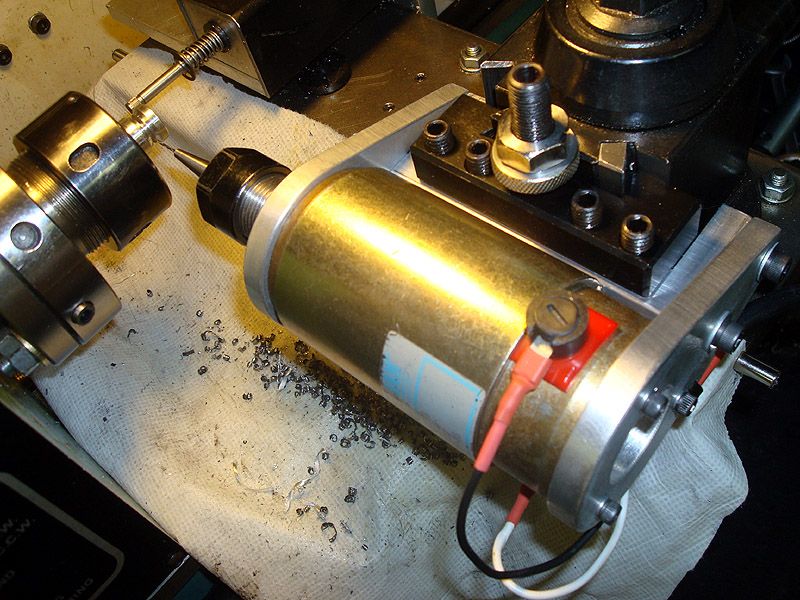
I built this thing up recently with stuff I had lying around to save some time when making model airplane engine venturis for a friend.  The venturis have 4, #58 holes in them and I’d been drilling them in the mill using a square ER32 collet block.  It worked fine but my mill’s top speed is a bit slow for the little drill and it required tedious setup for each one.

With the part still chucked in the lathe and the hang-on QC drill’s offsets stored in Mach, it’s now easy-peasy with a little bit of g-code to drill the holes right on the money.  I just mark the 4 positions on the chuck flange with a magic marker and use a simple wire pointer to index the holes.  Their positioning isn’t super critical and there’s not enough torque generated from the little drill bit to move the lathe spindle around while drilling.

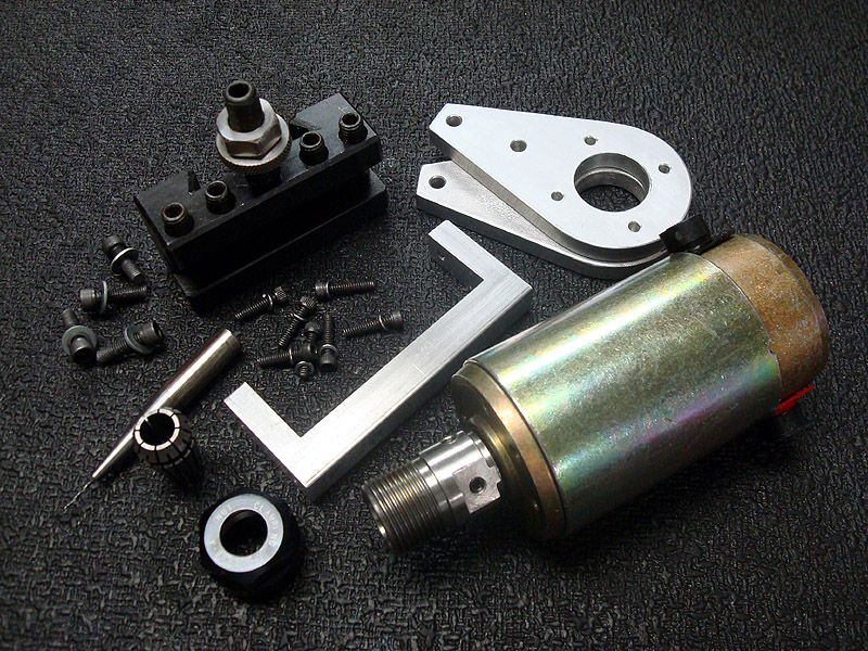
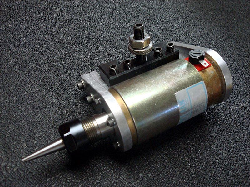
The motor is a 24VDC 3450 rpm Pittman given to me by forum member Jim Glass, thanks Jim!  I run it with a cheap ebay KB controller that I ordered by mistake.  It came with a Peco add-on board that runs off 36VAC so I used an old 36V transformer to power it.  With a few tweaks I got the motor running at a bit under 5000 rpm.  Still slow but it’s twice as fast as the mill & zips through aluminum like butter.  I tested it with bits up to 3/16” dia and they do great.

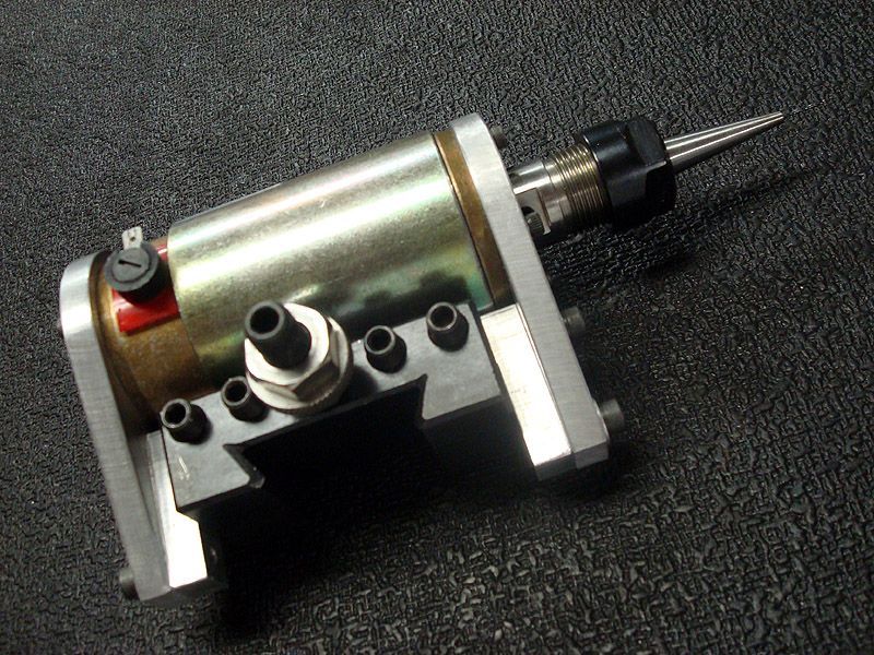
I made an ER16 chuck for it and was going to just press it on the motor shaft but my .3115” reamer somehow made an oversize hole.  Excessive chip buildup I think.  Anyway I drilled & tapped it for 4 setscrews and with a lot of cussing got the runout down to .0002”.  I would’ve liked to have used ER11 but don’t have the collets.  The drill bit holder shown was originally made to use in the mill but I’ll now make a shorter one to give more clearance.  The z-axis homing probe comes too close to the part for comfort.  If I bend that probe, after making a new one I’d then have to reset all 15 tools’ Z offsets, YUCK!


18
General Mach Discussion / X-Axis Peck Drill in Turn?
« on: April 20, 2015, 02:32:16 PM »
I'm in the thinking phase of cobbling up a QC toolholder with drill motor for cross-drilling 4 #57 holes in some small parts I make from time to time on my ORAC.

Presently I do the lathe ops, mount the part in a square collet block & drill the holes using the mill at the highest speed.  If I can rig a small high speed motor in the QCTP & manually index/lock the spindle the drilling could be done under CNC control.

Is there a way to make the X-axis do peck drilling without a computer science degree?

19
General Mach Discussion / Analog servo spindle drive questions.
« on: March 21, 2015, 10:49:50 AM »
I have purchased an AMC BE25A20AC Analog Servo Drive to replace the KB SCR speed control on my lathe.  Got decent deal on it and want to install it place of the KB to stabilize the spindle speed.  I have a week before it arrives to bone-up on the installation.

I plan to leave the existing Baldor ¾ hp PM DC motor & its belt drive system in place.  I had previously installed a Servo-Tek 7v per1000 rpm tach generator on the Baldor and plan to use it for the velocity input to the drive.  I have no plans for spindle positioning with the drive at this time, just accurate speed control.

Baldor says my motor’s armature inductance is 7.098 mH at 90V/.75HP and the AMC manual says “Minimum Load Inductance, Line to Line” is 250µH. 7.098 mH is way more than 250µH so I should be OK with that motor yes? Or do I have it backward?  I have very little understanding of inductance figures.

The drive’s speed & direction is controlled by a +/- 10V input which my CNC4PC C11 happily provides the positive direction for, but not the negative. I’ll need to reverse the C11’s 0-10V output polarity via DPDT relay for reverse spindle direction commands, yes? I already have a reverse-polarity relay wired up to reverse the tach/gen input signal to the existing KBMM drive so it should be easy to rewire it if that’s what I need to do with the servo drive.

Even though the drive is described as being brushless type, the manual says it can be used with single phase brushed motors by switching the commutation DIP switch to 60-degree phasing.  It’s unclear though, which of the 3 (A, B & C) motor output terminals to use.  Hopefully it either doesn’t matter or I’ve missed it in the manual & can find it later.

I was able to attach the drive basic manual but the one with more detail is too big?

20
General Mach Discussion / Lathe Tool Table tip radius/direction question.
« on: February 22, 2015, 01:07:21 PM »
I use Dolphin CAM to generate the code for my lathe and have all my tools with their tip radii & direction setups saved in Dolphin.  I have the tool X & Z offsets saved in the Mach Tool table but noticed today that I don't have their tip radii & directions saved. :-[

Will the Dolphin generated toolpaths (with tapers or radii in the work) all be incorrect because of that?  If not, surely any Mach Wizard generated code with tapers or radii will be wrong, yes?  Will I need 2 tool tables?

Just when I think I'm getting this stuff clear in my head, I realize how very little I know. ::)  Fortunately, it hasn't made much difference in the low precision work I've turned out so far but I need to get this issue correctly sorted.

Also. is the Direction box in the standard Turn Tool Table screen input expressed in degrees from 0?

Pages: « 1 2 3 4 5 6 »