1
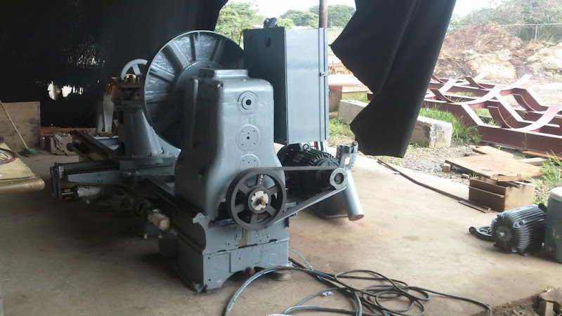
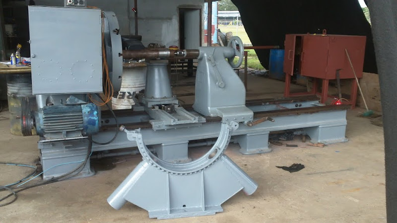
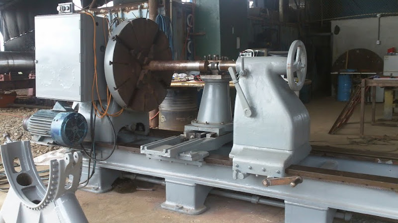
Show"N"Tell ( Your Machines) / Re: CNC Large Lathe Conversion pictures
« on: January 05, 2011, 10:55:11 AM »
Hello everyone!
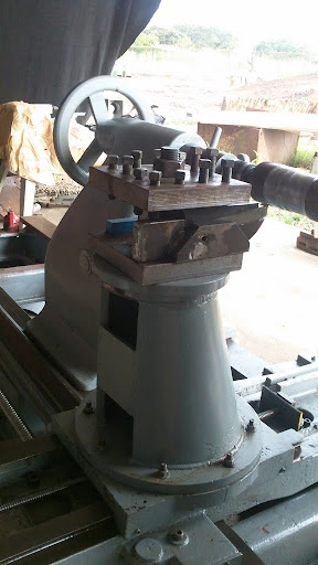
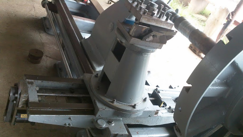
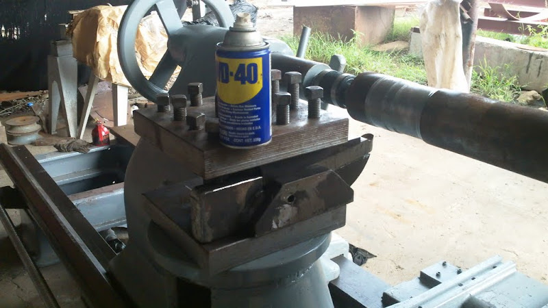
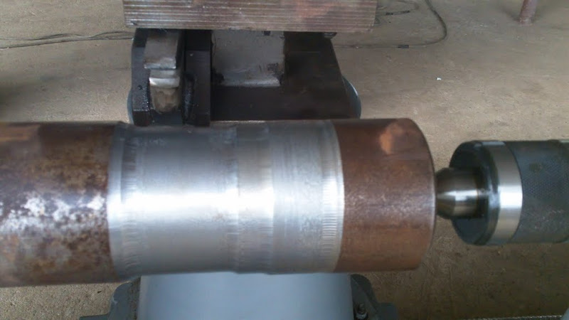
Last night I did the first tests of the lathe using lazyturn and machturn. I gotto tell ya lazycam is much more functional than I expected. The video was done at night, so its a little dark and grainy (sorry about that) but I couldn't wait till today to test it. In the video, a 50mm radius bar stock has already been brought down to 47mm in one pass and the video starts at the next pass which is 3mm deep with a 15mm feed rate at 164 spindle rpm. The tool is a 1" high speed steel blank I had laying around (I didn't want to test on $100.00 inserts ). I did a quick and dirty groover grind on it and slapped it on with a little angle to hide the face and cut with the leading corner as if it were the tip on a bit. There was a little chatter, but I attribute it mostly to the small tool (we usually use 2x2 and 3x3 tooling) and that my grinding was piss poor. I haven't installed the coolant system yet so I just cooled down the work with a little 140w when the chips looked like they were coming out too hot. Even though the tooling wasn't even close to being the right one for that type of cut and had no coolant, I did 2 more passes and pulled it to see and it was still pretty sharp. I was guessing it would last one or two passes at most.
<a href="http://www.youtube.com/v/D3JaiqHLLeE?fs=1&amp;hl=en_US&amp;rel=0" target="_blank" rel="noopener noreferrer" class="bbc_link bbc_flash_disabled new_win">http://www.youtube.com/v/D3JaiqHLLeE?fs=1&amp;hl=en_US&amp;rel=0</a>
Last night I did the first tests of the lathe using lazyturn and machturn. I gotto tell ya lazycam is much more functional than I expected. The video was done at night, so its a little dark and grainy (sorry about that) but I couldn't wait till today to test it.
In the video, a 50mm radius bar stock has already been brought down to 47mm in one pass and the video starts at the next pass which is 3mm deep with a 15mm feed rate at 164 spindle rpm. The tool is a 1" high speed steel blank I had laying around (I didn't want to test on $100.00 inserts ). I did a quick and dirty groover grind on it and slapped it on with a little angle to hide the face and cut with the leading corner as if it were the tip on a bit. There was a little chatter, but I attribute it mostly to the small tool (we usually use 2x2 and 3x3 tooling) and that my grinding was piss poor. I haven't installed the coolant system yet so I just cooled down the work with a little 140w when the chips looked like they were coming out too hot. Even though the tooling wasn't even close to being the right one for that type of cut and had no coolant, I did 2 more passes and pulled it to see and it was still pretty sharp. I was guessing it would last one or two passes at most.