Hello Guest it is April 26, 2024, 08:44:47 PM

Show Posts

This section allows you to view all posts made by this member. Note that you can only see posts made in areas you currently have access to.


Messages - hemi43

Pages: « 1 2 3 4 5 6 7 »
31
;D  >:D  ;)


It's just hot blonde and sweet with a little extra coolant mixed in.    ::)


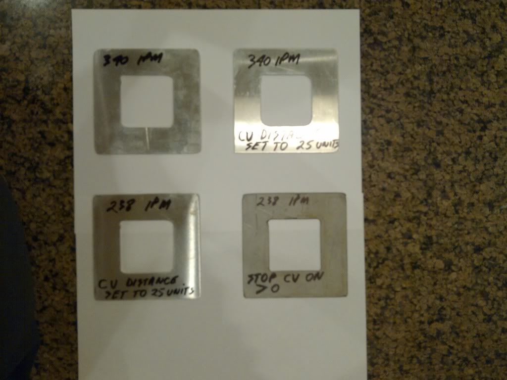
Even slower with CV bascially off the cut is a bit rough on the corners and seems to be squirly on the staright cuts BUT that might be the pictures.

It looks as thought the cut height may be too high and the arc is not stable. What are the cut paramaters? Material ?pierc ,cut preset voltage,etc

Are you running with the DTHC active ?  It it maintaining voltage?

(;-) TP

All the parameters are by the book, except for the speed that I had to slow down. All the pieces I've been cutting are .060 aluminum. The last piece was steel because I had no more scrap aluminum kicking around. :-)

DTHC was turned on, and maintains a steady pre-programmed 117 volts. My pierce height is .15 and cut height is .060.

Maybe the parts above are a bad example, because I'm very happy with the cut quality.

Dan

32
OK;
I ran some test pieces, and here's the results.
I hope the picture is clear enough. I tried running the first part at 340 IPM, but it was just too fast.
The second one I turned the CV distance on and set it to 25 units (whatever a unit is , I dunno).Also, I re-drew the part so that the inside corners have a .125 rad.
The third I slowed it to 238IPM. Still no difference.
The last one I checked off the "stopCV ON >0". The results were way better, and something I could live with. It's only thin material that will be an issue anyways.
The machine didn't seem to run any harder than normal.
Dan


33
Look at the posted code. The re is ONLY one operation listed in all the code and that is an OUTSIDE cut.

That tells me that when you cammed it out in Scam you did NOT set up a layer and operation for the inside cut but used the outside offset process to do everything.

So it really did NOT cut where you thought it would.

It would treat an outside cut differently from and inside, MAYBE

Just a thought, (;-) TP


Sheetcam automatically cuts inside profiles on the inside, and outside profiles on the outside, when outside offset is selected ( That's a mouthfull )
If what you're saying is correct, then my pieces would not be to size. My pieces are perfect except for the rounded corners.

Dan

34
I guess yall missed the part where he used an outside offset for and inside cut? That CAN throw a monkey wrench in the way Scam sees and programs a cut.

We use a similar size table and hardware electronics and DO NOT see this problem here.

Just a thought, (;-) TP


Hmmm !!! I am using outside offset, but only for outside contours. Inside contours automatically get cut on the inside.
Had a busy day and never tried anything on the machine today. :-(
Dan


35
Ahhhh !! Yeah, that's an easy way to fix the problem !! Why didn't I think of that ?? ;)
I will try that.
Dan

36
Those arc were put there by my CAM, which I forgot to mention is from Sheetcam.
I will check to see if it's possible to create arcs for inside contours.
I'm sure I could manually modify the g-code, but I don't really want to go down that road. ;D
Dan

37
Thanks so much Stirlling !!
I checked the G code for arcs in the small cut out, but never thought of checking the outside corners.  ::)
I understand clearly what you're saying, and I don't have an issue having a small radius on my parts, because this is a plasma machine afterall and not a waterjet.
The radius I have been getting (about 3/8") was just too large and would ruin the part. I would be happy with a 1/8 radius.
I will draw a small sample part today and try some of your recomendations.
I will post back my results.
Thanks again for your time, it's greatly appreciated.
Dan

38
Thank-you Stirling !
Any help is greatly appreciated.
I will try and mess around with some of the points you made earlier.
Dan

39
Thanks guys;

Instead of describing the machine, I'll post a picture. It's not an industrial machine, it's one I built.
I made the gantry from aluminum to keep the weight down. Aproximate weight is probably 50Lbs .
I run dual 960in/lb steppers for the Y axis and one for the X.
The Cad/CAM program I'm using is Dolphin Cad. All my electronics are from CandCNC.

Here is the g-code. I changed the speed to 200IPM from the original 350IPM.
You'll notice that the Post Processor did not program radiuses in the corners.

Thanks for having a look.
Dan


N0000 (Filename: Flight box side.tap)
N0010 (Post processor: MP1000-THCdan.scpost)
N0020 (Date: 29/01/2012)
N0030 G20 (Units: Inches)
N0040 G53 G90 G40
N0050 F1
N0060 (Part: Flight box side)
N0070 (Process: Outside Offset, Layer0, T2: .060 ALUMINUM Jet tool)
N0080 M06 T2 F200  (.060 ALUMINUM Jet tool)
N0090 G00 Z0.5000
N0100 X6.2300 Y2.9800
N0110 Z0.1500
N0120 G28.1 Z0.12
N0130 G92 Z0.0
N0140 G00 Z0.0940
N0150 G92 Z0.0
N0160 G00 Z0.1500
N0170 M03
N0180 G01 Z0.0600 F360.0
N0190 X4.2700 F200.0
N0200 Y0.5200
N0210 X6.2300
N0220 Y2.9800
N0230 M05
N0240 G00 Z0.5000
N0250 X10.5000 Y8.2700
N0260 Z0.1500
N0270 G28.1 Z0.12
N0280 G92 Z0.0
N0290 G00 Z0.0940
N0300 G92 Z0.0
N0310 G00 Z0.1500
N0320 M03
N0330 G01 Z0.0600 F360.0
N0340 G02 X10.5200 Y8.2500 I0.0000 J-0.0200 F200.0
N0350 G01 Y0.0000
N0360 G02 X10.5000 Y-0.0200 I-0.0200 J0.0000
N0370 G01 X0.0000
N0380 G02 X-0.0200 Y0.0000 I0.0000 J0.0200
N0390 G01 Y8.2500
N0400 G02 X0.0000 Y8.2700 I0.0200 J0.0000
N0410 G01 X10.5000
N0420 M05
N0430 G00 Z0.5000
N0440 X0.0000 Y0.0000
N0450 M05 M30


40
Thanks Stirling;
I know for a fact that my CAM is not putting an arc on the outside corners, and that's why I'm confused about this.
There is such a huge difference in radius size between inside and ouside corners at the same speed. I think I will have to learn to cut at slower speeds, but I was hoping not too.
Dan

Pages: « 1 2 3 4 5 6 7 »