Hello Guest it is April 25, 2024, 09:17:17 PM

Show Posts

This section allows you to view all posts made by this member. Note that you can only see posts made in areas you currently have access to.


Messages - freedom2000

Pages: « 1 2 3 4 »
21

i think there may be a serial out command that is supported by mach in vb, its either serial out or in because i remember looking at it to see if i could get the plasma volatge in that way but i couldnt get 2 way communication.

In some ways i doo like the idea of referencing the voltage fromt he start of the cut too, saves a lot of messing, you just leave it to do its thing, set the feedrate to what gives you best results and it does the rest, i think it would be very interesting to be able to see what that was doing until you learned to trust it, for instance if i make 5 pierces and start cutting do i get pretty well the same voltage preset each time?? how close is it to what is in the book?? etc etc...

keep up the good work jp

Hi Matt,

I have found a way to send informations from Mach3 to the serial COM you want. Just copy paste this code into any button and run it :

Sub main()
  Set MSComm1=CreateObject("MSCOMMLib.MSComm")
    MSComm1.Settings = "9600,n,8,1"
    MSComm1.CommPort = 5
    MSComm1.InBufferCount = 0
    MSComm1.PortOpen = True
      If Err Then
         MsgBox "COM" & MSComm1.CommPort & ": not opened, Sorry!"
         Exit Sub
         Else
         message "port opened"
          Sleep(1000)
         'MsgBox "COM" & MSComm1.CommPort & ": opened !"

      End If
    MSComm1.Output="Torch Voltage sent by JP : " & GetOEMDRO(83) & Chr(13)
    'MsgBox "COM" & MSComm1.CommPort & "output ok"
    message "torch voltage sent"
    Sleep(1000)
    MSComm1.PortOpen = False
   
    Set MSComm1 = Nothing
End Sub   


The port that I choose is port COM5, you can change it if you don't have COM5...
I have checked that it works, the port is properly receiving the DRO value.

BTW, what are the DRO's for THC ?

I will try to update my PIC code to monitor the voltages as you propose.

Cheers
JP

22
Jp,

Personally id like to be able to set the voltage from mach for each cut, you could communicate it to the pic either using an analogue output if you have a modbus device or by using binary over 5 or 6 inputs, just a thought, be sure to let us know how you get on

Matt

Well,

My Pic is fully used (in terms of IO pins), I only have one remaining input pin left...
I could use it to communicate with Mach3 using serial protocol RS232
I know how to do it with the PIC but not from Mach3 ...

May be with a script, but how ?

Any idea  Matt ?

JP

23
JP,
I like it, i like it alot....

You tie the bridge to power supply negative to make them common, i had wondered about it but never imagined you could do it without having problems like drawing loads of current or destroying the pic when you fire the plasma, youve just solved a wholeload of problems!!!

The killer partnow really is in the filtering of the voltage from the torch to take out any spikes or component destroying hf.

I presume you are planning on using the pic for ad conversion then feeding the frequency output to mach through the pp??

Id love to see how that works

Matt

Thanks Matt !!!

By the way the pic is protected for under and overvoltage with internal dodes put on all the I/O pins --> there is almost no way to destruct it (if the intensity of current is within the range...)

I need to filter the voltage only to get a proper measure to make the THC work !

I will not send the "index" signal to Mach3 but only the UP/DOWN and torch OK signals.
All the computations can be done in real time into the PIC.

The tricky issue is that I will not have the "Voltage consigne" from Mach3 either...
But I can monitor the firs ms of cutting when the torch is properly positionned in height and when there is yet no significant deformation of the metal.
So :
- mach3 height positonning
- piercing
- start of move
- PICK UP of torch voltage and use it as reference
- monitor torch voltage and deliver UP/DOWN signals

JP

24
Hi all,

Rather than trying to convince myself (or you !) on "voltage stories" I decided to try my schema   ???

Here is the result on you tube http://www.youtube.com/watch?v=8w3nAoKZghw

It's only a prototype just including the voltage divider that I had put after the bridge rectifier.

The Vss is connected both to the minus signal of the bridge and to the minus power supply of the PIC (exactly as on my schema)
The PIC itself is powered by a small mobile phone 220V to 5V DC power supply

The analog to digital input is used to flash two leds :
- one indicating a torch voltage between 40V and 150V
- one indicating a torch voltage greater than 150V (off if Vtorch < 150V)

The input torch voltage is absolutely not filtered so a few spikes may occur... But the basic function is demonstrated  ;D

Why does it work ?
Because a "voltage" by itself is nothing... it must be "voltage difference". When wiring together the 0V of my PIC and the minus of the bridge output, I fix the "minus bridge" to 0V
When some electrons are flowing from the bridge minus to the bridge +, then the bridge v+ climbs, thus it is seen as a signal between 0 and 5V on the divider.

I have also connected an oscilloscope on the bridge and measured the signals between :
- the plasma ground and the torch tip --> it's a negative voltage (as foreseen)
- the bridge - and the bridge + --> it's a positive signal (as foreseen)
- the plasma ground and the bridge + --> it's a negative signal ... but I don't use it  :-\


JP


25
Great idea Matt !

Regarding the PID I think it's easy to do the job into the PIC, but would need a "speed signal" to be output for Mach3 to get the result information in addition to the UP/DOWN pins

For the I/O to/from Mach3 of "bytes values" an easy way would be to use serial COM (at least with a PIC it's easy to do). Don't know yet if Mach3 supports serial COMs but I suppose that yes !

JP

26
Matt,

I am surprised too, but I trust you !

I will ask this question to an electronics ingeneer I know (and specialized in high voltages) ... we probably could get more explainations on this topic.

However why do you measure with true ground as a reference ? (I understand the VSS signal being the ground)

On my plasma the ground (of the plasma box device) is not connected to any pin of the plasma torch.
Of course the metal piece to be be cut will be connected to the CNC ground... but from an electrical point of view the + and - signal of the torch are not if you isolate the metal part to be cut from the ground.

JP

27
Hi,

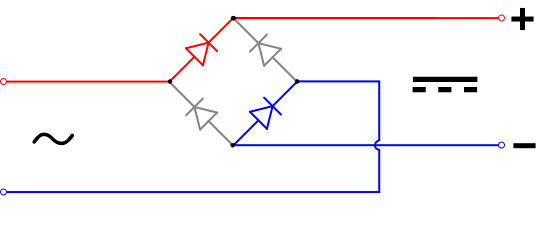
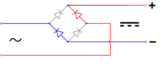
The bridge rectifier is basically useless if you are sure of the polarity of your plasma... If not (or if you have doubt like me) then the bridge is simply protecting the output to possible reverse polarity insuring in a systematic way that the + output side will always be positive and the - always negative.

See here some more explainations : http://en.wikipedia.org/wiki/Diode_bridge


in particular check this sentence : In each case, the upper right output remains positive and lower right output negative. Since this is true whether the input is AC or DC, this circuit not only produces a DC output from an AC input, it can also provide what is sometimes called "reverse polarity protection". That is, it permits normal functioning of DC-powered equipment when batteries have been installed backwards, or when the leads (wires) from a DC power source have been reversed, and protects the equipment from potential damage caused by reverse polarity.

So whatever the polarity of you plasma is the bridge will insure that the input to the ADC is always positive.

Agreed ? (it was not so easy for me to admit it...but it's the basic  principle of a diiode bridge)

JP

28
Jp - i like it, the only thing im wondering about is the polarity of your plasma voltage, my cutter is negative polarity, if yours is you need to connect your voltage divider to vdd not vss, so the arc will pull the voltage down.


Hi Matt,

As I have put a bridge rectifier, I don't think that I need to pull up the signal. I have already measured the bridge output and the voltage is positive when I plug the "black wire" to the Vss.
Furthermore I input the divider into an analog to digital converter, so I suppose that I can handle the output "logically" ...

Cheers
JP

29
Hi all,

It's a long time since I have not posted here  ;)

I have practiced a bit on µcontroler since this summer, and thus I plan to give up my original design (with LM331) for the benefit of a simpler and more powerfull Pic based circuit.

I plan to use a PIC 12F675 (2 $) to perform the following functions :

- output torh up and torch down
- output torch OK signal
- input torch intensity (with hall effect sensor) (use Pic comparator to convert it to torch Ok signal
- input torch voltage through a voltage divider into the Analog to digiital Pic IO and elaborate the UP/Down outputs

As you can see all outputs are opto protected
the torch ON signal is sent diectly via a relay to the plasma (not controled by my electronics (also I could as there is one input left opened !)
I plan also to use the original Port 1 of my PC assuming that there is no need to add an extra one...
Why ?
Just because :
- I can put the extra Zero Z torch in serie with the X, Y, Z limits switch of my CNC
- I will not input the torch voltage to Mach3

The software will do the following :
- monitor the torch intensity and wait for "torch OK"
- if torch OK :
   - waits a few seconds for the voltage to stabilize after peircing
   - monitors the torch voltage and use it as a reference
   - loops on voltage measure + average (filtering) and outputs UP/Down signals
until torch NOK

Assuming that the Gcode is OK the height should be correct after peircing and consequently the first monitored voltage could be used as reference
There is thus no need to have the Voltage provided by Mach3
Also the upper and lower limits for generating UP/down signals could be generated by the pic

For the Torch OK signal I plan to use a cheap and very simple hall effect sensor UGN3503 (made by Allegro)
It is a "stand alone" device which only needs +5V power supply and outputs directly a voltage deviation from 2,5V reference if a magnetic field is seen by the sensor.
It can be used with a toroid to sense current in a wire


The toroid is extracted from an old PC power supply and a slice of it is removed with a dremel. It acts as a magnetic field concentrator into wich is inserted the sensor.
See how small this device is compared to a USB key  ;D


And finally the virtual PCB  ;)


Hope all this will work !

JP


-

30
Hey guys
 Did you get your DTHC working

Hi,

Well not yet... Still finishing my CNC. See it's first cut here : http://www.youtube.com/watch?v=ILIp6wt-FJ4

JP

Pages: « 1 2 3 4 »