Hello Guest it is April 27, 2024, 04:23:28 AM

Show Posts

This section allows you to view all posts made by this member. Note that you can only see posts made in areas you currently have access to.


Messages - stevehuck

Pages: « 1 2 3 4 5 6 7 8 9 10 11 12 13 14 15 16 17 18 19 20 21 22 23 24 25 26 27 28 29 30 31 32 33 34 35 36 37 38 39 40 41 42 43 »
331
What size Cap Screws are you using? Looks like #6-32
and I assume you wont be using any paper gaskets?
Fun project to watch being built.

They are #2-56

I make my gaskets, including head gaskets, out of teflon sheet. Heads will be .020 thick and all others will be .010 thick.

332
I made the timing cover today. The cover was cut using the CNC machine then the counterbores were made manually in the drill press. I now have to chuck it up in the lathe and bore the inside to recieve the front crank seal. I think the cover will be polished and buffed to a high gloss. 


333
Looking forward to the transmission build,  ;)  excellent project, keep up the fine work.

I'm looking foward to the transmission build also. Which one of you is building one?

334
NEAT. Lookin real good.

 What material did you use for the 4 bolt bearing caps?

I use 6061-T6 for almost everything.

335
Got a bit more done on the block. I went down both sides of the block with a 5/8 ball nose to give the block it's final profile.


Then with the block upside down, finished the profile.


Then i knocked down the pointed edge in the valley to make it look a bit nicer.


I think for now the block is done. I still need to drill the hole for the distributor but i'm going to wait and drill thru the manifold and block at the same time. It just hit me how small this thing is.


336
Doesn't matter how you do it Steve, It looks really good. And 5 hours is fast for a cam project.

Keep it up.

Dont get me wrong, I am open minded to it. If I had a 4th I might try it just to learn something new. I also want to make some blower rotors in a rotary axis but i have none.

337
Steve the way we do it here is generate the lobe profile. Load the blank into the 4th between centers. Rotate to a start point on the blank. Cut the profile onto the first lobe. Move over in X to the next lobe rotate the cam to orientate the next lobe center and cut that lobe then on to the next. Once you start it is very easy to index the separate lobes at the proper lobe centers. IF you want a split profile just substitute the intake profile for intakes and exhaust for exhaust.

I am sure your process works for you but 47 cuts per lobe?? that is a lot of setup(;-)

Keep us up to date on your project.  Mini's look cool but I will stick with the big boys

The Cam in the posted picture was made start to finish in 5 hours. Even if i had a 4th I'm not sure i could create the Gcode in 5 hours. I'm still real new to all this "drink beer while the machine does it all" stuff. This is just one of those times where it is faster to do it manually.

338
I would definitely do the crank in a lathe. The cam lobe profile in a mill.
The tedious  part is getting all the cam lobes in the correct orientation on the shaft.

How much valve lift will this engine be running? and what ratio rockers. Curious.

Take a look at this. It is alot easier than you think.
http://www.mikes-models.com/camarticle.html

.070 lift  280/280 duration 110 seperation

339
(;-) Your lobe must be correctly designed to run with your lifter. The curve is the actual ramp of the lobe. You can run right up to the edge of the lifter with the ramp design without problems.(;-)
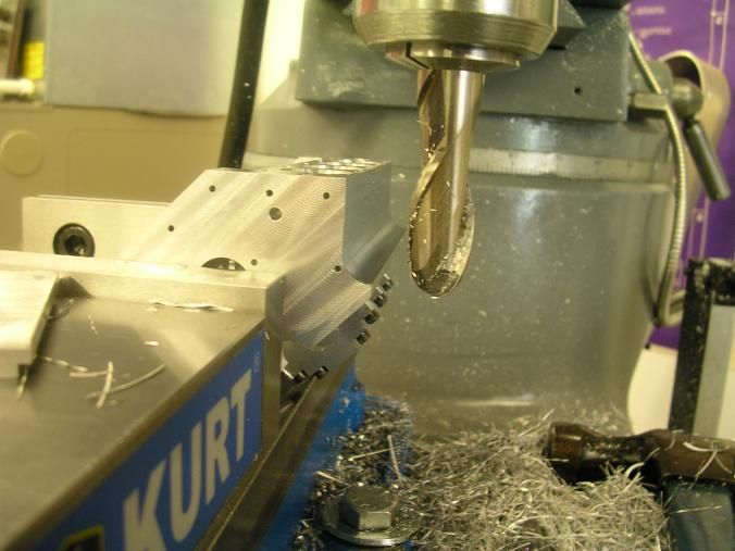
You are talking about a curved flank lobe. We are on the same page. I have milled a cam with a curved flank and i have made them on the lathe and the lathe is about 4 times faster doing it the way i do. I do make one piece cams, not the built up type. Nothing wrong with them, I just perfer the one piece design

Alot of guys just cut into a lobe, turn the lobe, and then cut there way out making a lobe with flat flanks. It is faster but the time spent making roller lifters or ball nose lifters needs to be added in.

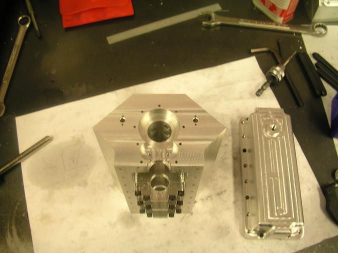
This cam was made for a V4 i finished a few months ago. I get alot of positive comments on the sound.

http://www.youtube.com/watch?v=1-JRQGPswVA


340
Steve we have run flat lobed cams and flat lifters well over 11k rpms in race engines.

How do you keep the edge of the lifter from digging into the cam lobe? something needs to be curved or the edge of the lifter will meet the cam lobe and gouge the surface.


Pages: « 1 2 3 4 5 6 7 8 9 10 11 12 13 14 15 16 17 18 19 20 21 22 23 24 25 26 27 28 29 30 31 32 33 34 35 36 37 38 39 40 41 42 43 »