Hello Guest it is April 26, 2024, 04:27:19 AM

Show Posts

This section allows you to view all posts made by this member. Note that you can only see posts made in areas you currently have access to.


Messages - stevehuck

Pages: « 1 2 3 4 5 6 7 8 9 10 11 12 13 14 15 16 17 18 19 20 21 22 23 24 25 26 27 28 29 30 31 32 33 34 35 36 37 38 39 40 41 42 43 »
221
I hate myself but odd number blade setup will be much smother.

even number work on dc/aux setups but many are odd too.

is that a torsional front hub/balancer?

made my year :)

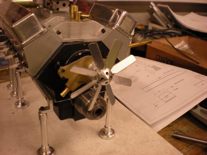
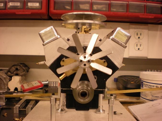
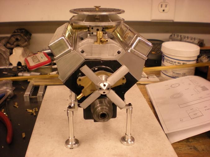
When you build your V8 you can have as many blades as you want.  Haahah!!  The 8 blades actually came from a member of another board. Said something like "if I made one it would have 8 blades because" so I was making a new one anyway. I made it to his spec and posted it mounted on the engine the same day.  Now he is making a 9 blade. I already have a design for a 13 blade if the hint of a challenge is made.

That is a mock balancer/pulley. It houses a clutch bearing so I can start the engine.

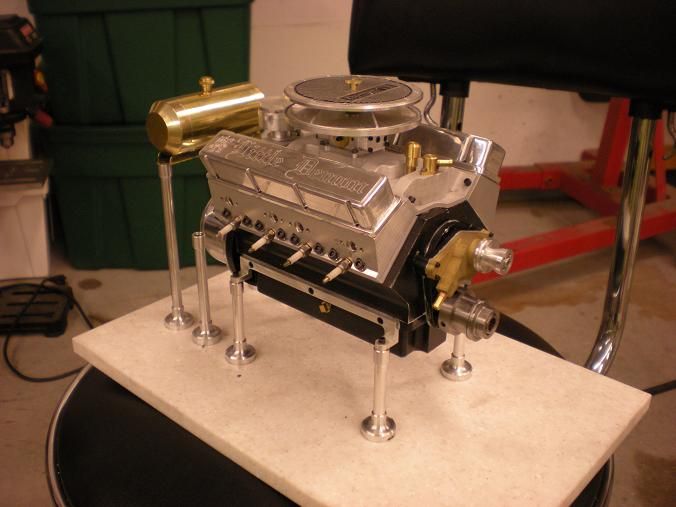
Have you seen the guy at CNC Zone who is building this engine at 1.5:1 scale? I think he will finish before me.

222
Didn't like the fan so I made another


223
Very nice work Steve and I hope your pleased with the results.
RICH

I might try to make it black somehow.

Fan is done!


224
Good stuff, Steve. I see you've got the cherry picker behind the stool ready to go.

That's an engine stand. It was the basis for the stand for the Co2 V8


225
Fuel tank is mounted.


Radiator is done but still needs to be mounted.


226
A little bit more fancy then?

How fancy can you get with a fan?

at least a bit more curvature...


I'll see what I can do

227
That looks nice, awesome work! :)

Thank you

228
A little bit more fancy then?

How fancy can you get with a fan?

229
do i see a fan in the background?

Yep!  I didn't like it and plan to make another one.

230
Scratch fuel tank off the list!

Work was cancelled for the day so i made the 2 end caps for the fuel tank. They are just 2 slugs of brass but if you want to increase the capacity of the tank the ends could be bored out.


After polishing the tubing the holes were drilled for the filler neck and outlet fitting. I didn't call out the holes in the drawings because I felt everybody has a personal preference as to where the fittings go. The fittings were then soldered in from the inside.


I cant remember where i saw this but the inside wall gets fluxed and a piece of solder is wrapped around the inside of the tank. The end cap is fluxed and installed. The prepared end is set on the table and a torch heats until the solder melts and bonds that end.


The same process is used on the other end and then the tank gets soldered to the mount bar. I rubbed it a little on the buffer. There is alot more buffing to do but you get the idea.


Pages: « 1 2 3 4 5 6 7 8 9 10 11 12 13 14 15 16 17 18 19 20 21 22 23 24 25 26 27 28 29 30 31 32 33 34 35 36 37 38 39 40 41 42 43 »