Hello Guest it is April 29, 2024, 07:00:37 AM

Show Posts

This section allows you to view all posts made by this member. Note that you can only see posts made in areas you currently have access to.


Messages - cncfreakcncfrea

Pages: « 1 2 3 4 5 6 7 8 9 10 11 12 13 »
61
General Mach Discussion / SmoothStepper + C6 + Mitsubishi AC Servo MRJ2S
« on: October 07, 2013, 07:03:40 AM »
Hi,
     Need some help on wiring C6 speed controller to SS.
Current wiring:
Used Pin 6 and 7 for step and Dir of SS port 1 wired them to C6 X2 Input Signal Connector, in X2 there's a EN CCW what do I do with it?
Applied 24V to C6's power input X1.
Relay 2 (x7) is energised, NO.
The Spindle RPM is 0, by pressing arrow up or down, still 0.
Analog output (X4) measures 0.02V no matter turning cw or ccw of the VR (X5).
Mach3 settings:
1 - Config--->Ports&Pin--->Motor output---> enable spindle step pin = 6, Dir pin = 7, step Port = 1, Dir port = 1.
2 - Config--->>Ports&Pin--->Spindle setup---->Motor control box check use spindle motor output and Step/Dir output.
Disable Spindle relays is unchecked setM3 output =2 setM4 output = 1
3 - Config--->Spindle pulleys--->Pulley Number 1 Min =0,Max =420, Ratio=1.
4- Config--->Motor Tuning--->Spindle--->step per = 1000, Velocity=2700, Acc.=450.

Please provide an wiring diagram for guidances,

thanks.


62
Ok, I have been thinking a lot whether to use my servo drive in speed control mode or position control mode for spindle?
If I use speed control mode then I can use my spare C6 from cnc4pc to feed 0-10VDC to MRJ2S drive like this:


63
Check the wire connection, the Index terminal was connected wrong and has been corrected and previously the 0v wire is not wired to BOB's com (gnd), Index pin is flashin in Diagnosis.
http://s1204.photobucket.com/user/cncfreakcncfreak/media/BVB25L%20cnc%20conversion/IMG_3953_zps859e6a27.mp4.html

64
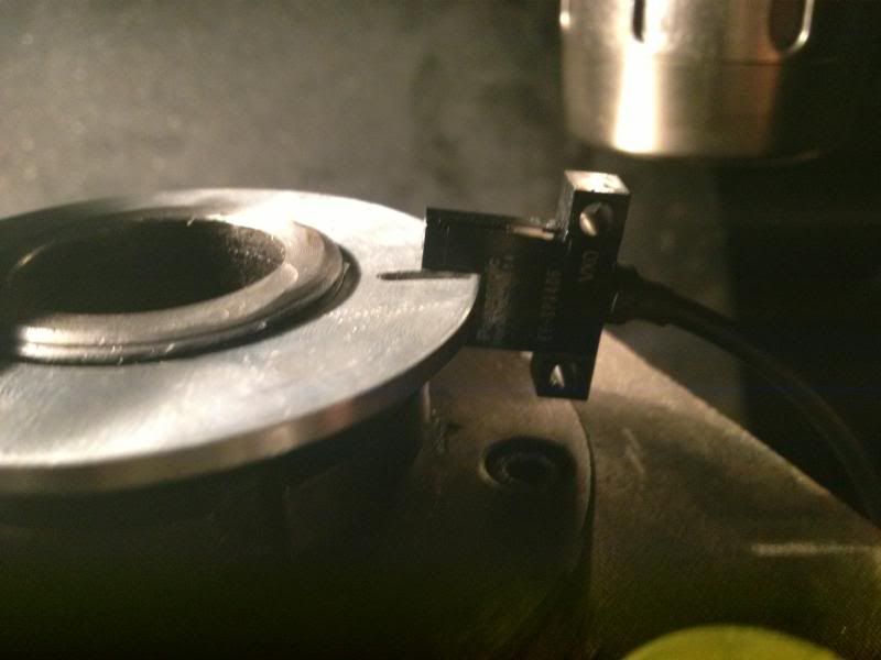
Ok, Sensor installed, EE-SPX406: http://www.ia.omron.com/data_pdf/data_sheet/ee-spx-w_dsheet_csm474.pdf
Wire: brown = 24V, Black = Index signal, Blue = 0V
I set the Index Input to pin 10 port 1, how do I determine if there's signal coming in to Pin10? Mach 3 turn no Diagnosis tab?

65
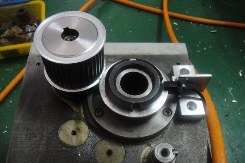
Add a sensor holder:


66
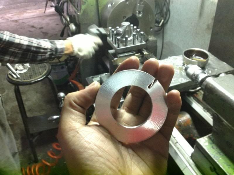
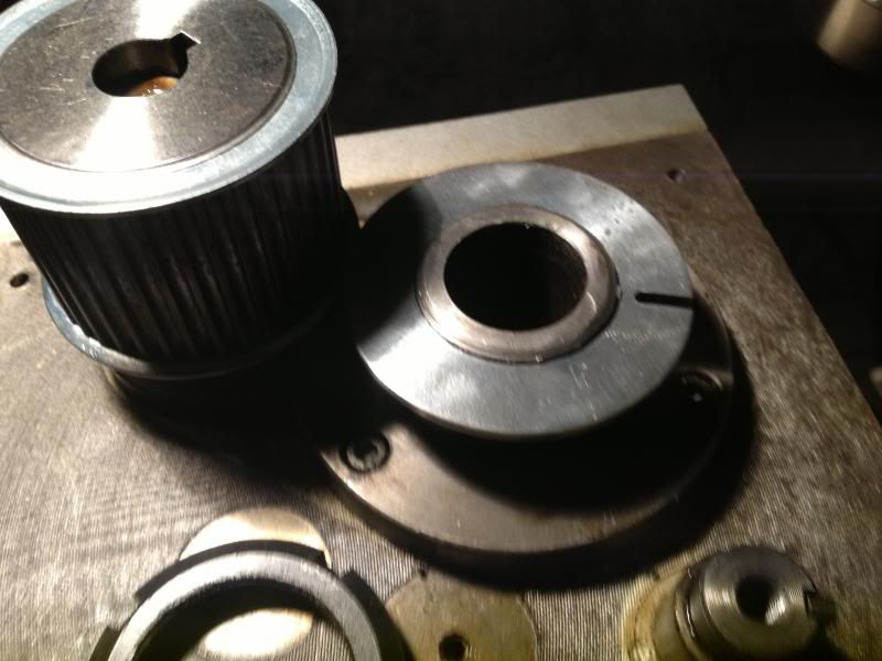
Had the Index Pulse Interrupter Disc made:


will continue with the sensor holder after I come back from holidays!

67
Hello I'm back, just had the X saddle drilled 6 threaded holes 3 each side for securing the cover.

68
The gantry was purchased as used about 2 years ago, is a 2.8m length, 1.8m wide, small machine compare to my neighbour's 5m long gantry. This machine only for facing, it is not suitable for positioning error is too large (lead screw).
Ill add a fan at the top of that amp some day.
I'm waiting for my new machine cover from Defender for the lathe:

http://www.machine-cover.com/products.htm

then will proceed encoder installation.


69
Hello Hood,
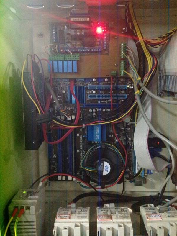
                I took some photos and videos of my gantry mill, the controller has 1 x C10 board + 6 SSR:


Video:
http://s1204.photobucket.com/user/cncfreakcncfreak/media/BVB25L%20cnc%20conversion/GantryMillMach3_zpsa9b556be.mp4.html

70
I checked some of my previous controller wiring, this one:


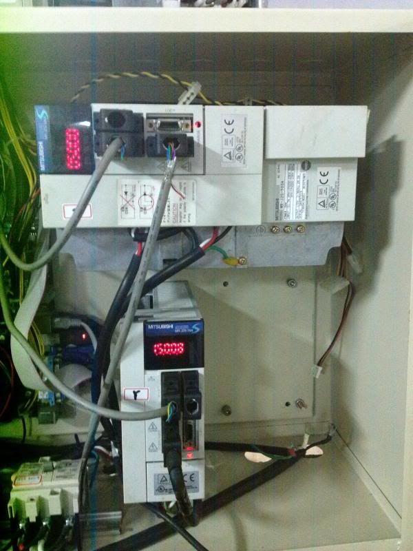
The SS had a C25 Terminal Board, MRJ2S's Amps worked.

Are you trying to send the step/dir signals via the relays?
Yes, the C10 board is wired this way and worked pretty well for MRJ2S so I used the same method for SS, but didn't work.

When you say it worked via the C10 are you meaning you had it connected via the parallel port or via the SS to c10?

http://s1204.photobucket.com/user/cncfreakcncfreak/media/BVB25L%20cnc%20conversion/M4V05950_zps587ff3dd.mp4.html
PC connected to C10 via pararell cable, then from C10 pins 2&3 to MRJ2S CN1A's CW & CCw result = link above.


Is the CN1A not the inputs for Step/Dir or are you talking about some other output from that connector?
Yes this is the input for Step/Dir coming from SS.

Have you set the SS config up for Step/Dir spindle?
I haven't done any changes in config. I disconnected one of the stepper driver's step/dir wires off SS terminals and wired CN1A's cw wire & ccw wire to the terminals and test if it spins, but it doesn't.


Pages: « 1 2 3 4 5 6 7 8 9 10 11 12 13 »