Hello Guest it is April 29, 2024, 05:14:58 AM

Show Posts

This section allows you to view all posts made by this member. Note that you can only see posts made in areas you currently have access to.


Messages - cncfreakcncfrea

Pages: « 1 2 3 4 5 6 7 8 9 10 11 12 13 »
11
Yes there are vias intacted.
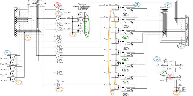
Yes I'm aware there are 2 separate power supply VCC and VDD, gnd 1 and gnd 2.

What should the value of VDD be? 7v?

12
Hi Craig,
            I will check the VCC and VDD later with multimeter, might get a Oscilloscope soon since I'm doing a lot of electronic project recently.
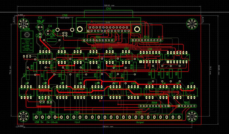
I use Diptrace 2.4.02PCB software, double sided works quite well in diptrace but not single layer, I tried before and was rejected by the pcb manufacturer 5 times due to short circuit. Single layer still works depend on complexity.

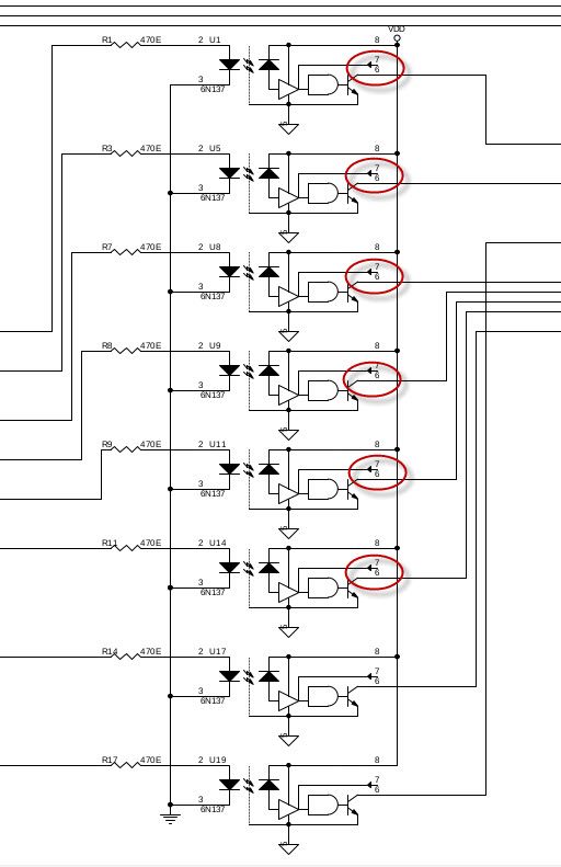
The pin 7 of 6N137 meant to be NC, is this correct?


checked Vcc Vdd Gnd1 Gnd2 in Diptrace schematics, looks alright..:

13
Let's forget the relay for the moment. I'm not sure if the following schematic works?
https://karusisemus.files.wordpress.com/2016/07/sch.png


The PC817 is replaced with 4N35, because I got some spare 4N35.
I have made the board with components soldered, but didn't work...


14
A quick question:
Is this schematic correct?
https://karusisemus.files.wordpress.com/2016/07/sch.png

15
mm....scratch did not work....

16
Ok I've just built a simple circuit in scratch, the only diode I have is a 1N4007N, is is ok?


17
Ignore the above I was describing a bob using SN 74act245N, totally different to 74Hc14, sorry..


18
Thank you for replying.
Tweakie,
This is more like a electronic project I wish to make it myself. Will look into protection diode, thanks.

Joeaverage

I did a test on a bob's pin 17 and gnd using a voltmeter for continuity, after entering Mach3 I measure Pin 17 and gnd no continuity, then I type M08 at MDI voltmeter beeping I get 5v, M09 to disconnect or off.
My output setings are:
Output #1   Enabled  Port 1   Pin17   Activ low = off


19
General Mach Discussion / add relays to Break out board schematics
« on: May 31, 2017, 02:45:46 AM »
Hello all,
            I have created a break out board schematics it is finished and I would like to add a relay for coolant/flood to pin 17, so when coolant is activated the relay clicks, is the illustration below correct?


20
found it, 74HC2450.

Pages: « 1 2 3 4 5 6 7 8 9 10 11 12 13 »