Hello Guest it is April 25, 2024, 01:56:37 AM

Show Posts

This section allows you to view all posts made by this member. Note that you can only see posts made in areas you currently have access to.


Messages - John Mac

Pages: « 1 2 3 4 5 6 7 »
31
General Mach Discussion / Rotary table dividing calculator
« on: January 28, 2012, 06:49:41 PM »
Hi All
I guess this is decidedly non CNC related however it may come in handy on your manual mill.
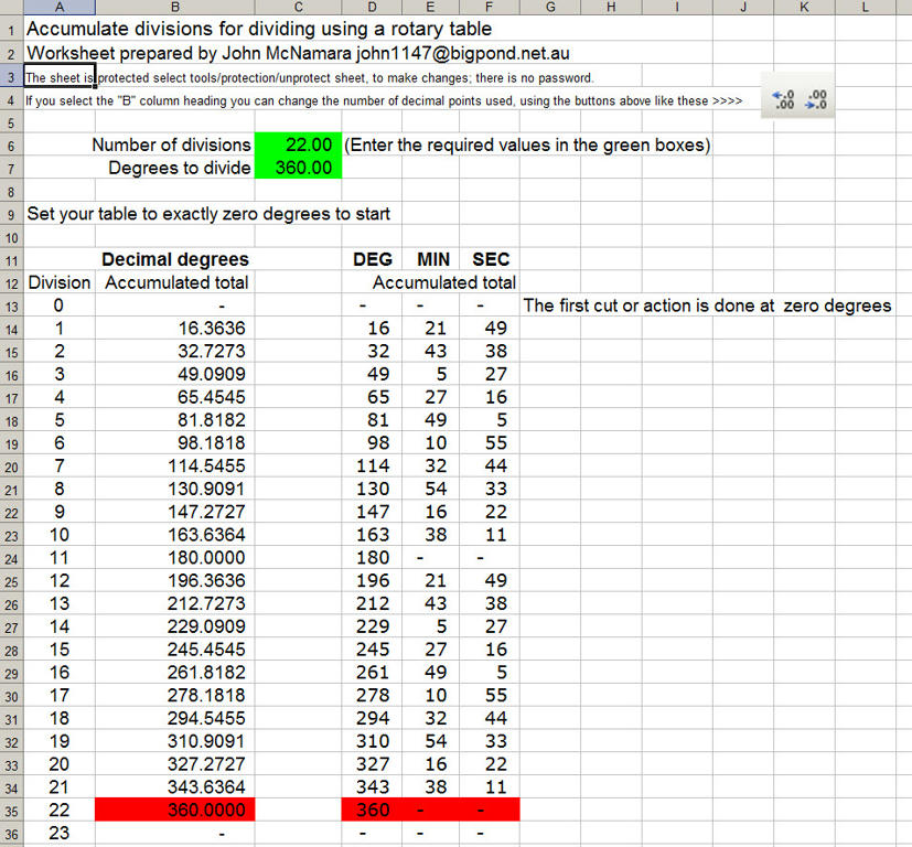
It is written in Excel (no macros) you can change it as you wish.
Enter the number of divisions and it will display all the decimal angles together with the same angle in DEG MIN SEC.

http://www.mediafire.com/file/yxheh2nvg2h3q7j/Dividing Calc 1.zip

Cheers
John


32
General Mach Discussion / Re: Speed & feed calculator
« on: January 27, 2012, 06:10:48 AM »
Hi All

Image of speed and feed calculator above:


Cheers
John

33
General Mach Discussion / Re: Speed & feed calculator
« on: January 27, 2012, 01:23:40 AM »
Hi All

I made this one up using Excel (You can change it)

It may help you if you want to make one up for a specific machine

If your machine has fixed feed rates you can edit the sheet and enter them.

http://www.mediafire.com/file/uxje635gjl5psee/SPEEDS and FEEDS - V2.zip

Cheers
John

34
General Mach Discussion / Re: Mach 3 Sewing Machine
« on: November 12, 2011, 01:02:34 AM »
Hi Larry

Thanks for your offer of assistance.

In  previous Life I bought a commercial CNC Quilter Resta H220 for my business. It was fairly old although the control system worked perfectly using a Z80 based processor. Interesting to think about that...... a few cards loaded with 7400 series IC's and the Z80 instruction code in Eprom. (Naturally I backed that up just in case). Over the 15 years we ran the machine it occasionally would develop a fault. No problem every part on the boards were easily replacable. No Surface mount stuff (Now so small it is almost dust) No multi layer boards with unfindable broken tracks. We never had to buy a replacement board.  

The minus was It used a proprietary instruction set to store programs and the instructions were obfiscated I guess they did not want to make it easy..... there was a PC based "Programming system" available for huge money or a hand programmer that was error prone. not a good option. Or you could order programs from the factory for a fee and a delay of a few weeks. the programs were delivered on "Eprom" UV erasable static ram.

I decided to make a project of it and design my own programming system via Autocad DXF into a CAM converter written in Visual basic that converted the DXF file into Resta Instruction code. It sounds easy......well it is not however after about 6 months research it was done!

And the patterns produced are dead accurate unlike the results from the hand teach mode programmer that was NQR.

I don't run the machine any more however I still have the programming system.

Cheers
John

PS:
The machine below is not the same machine but very similar, Except my machine was enlarged. We cut the main frame and made it 1200mm wider and rebuilt the rest of the machine to match it was a bit of a beast requiring 8000mm x 6000mm of floor space.    

35
Hi Cosha

I posted this elseware on this forum however you may find this interesting if you want to cast nuts:
http://www.mediafire.com/file/xpdu1z75t6hm70a/Bearing%20-%20MACH3.ppt

It is a method to make cast nuts. like below
Cheers

John


36
Hi All

I updated The Worden Design Table added:
http://www.model-engineer.co.uk/forums/postings.asp?th=51617&p=5

Cheers

John

37
Hi Jammerm and good to see you Tweakie.

I was borne in and live in Melbourne Australia, so they are not exactly "my guys", The Model Engineer forum is like any other public group. Some really gifted individuals and naturally its share of detractors. The Uk has and does produce some pretty good engineers both formally trained and hands on practical. I am one of the latter. It’s a pity that threads get taken off topic (As I am doing now) so maybe I should get back to the subject at hand. Building Epoxy Concrete based machinery.

A bit later, hopefully today I will post a further installment on The ME Site The table is now installed on the machine. The next component will be the Y axis feed.

The quicker I finish it the quicker I get back to my CNC mill design.

Cheers

John    

38
Hi All

In order to learn some of the methods of using Epoxy concrete, now often called “Mineral casting” I am building a small Worden tool grinder. You will find many references on the net. It will come in handy to grind lathe tools to the correct angle; however the build is not as it was originally designed. All the sheet metal parts for the frame have been replaced by 4 Epoxy concrete castings. Most of the detailed work is now done except for the table, some graduated dials, the y axis feed, the grinding motor itself and its epoxy concrete stand.

I have been documenting the build Here: (you will need to scroll back to the start and ignore the off topic comments hmm…..)

http://www.model-engineer.co.uk/forums/postings.asp?th=51617

Maybe the grinder is a bit off topic for this forum however the casting methods certainly are not. A litre and a bit of Epoxy and a bucket of aggregate and sand replaced a lot of sheet metal and made a much more rigid tool. The machine is really solid.  Note the cast in place low friction bearings.
 
The main objective is to get some hands on experience on a small affordable project before I tackle the CNC Mill using mineral casting.

When the machine is finished I will post a set of drawings.

Cheers

John


39
Hi Tweakie

Thanks for your support.

I have seen a lot of wood / Aluminium routers, however very few projects that can handle steel apart from conversions.

The question is where do we get that Spindle? The rest is not that hard to find.

The Epoxy bearing material will come in handy.
I guess the Epoxy Concrete is a little less critical than some would argue….And I am using plenty of Steel reinforcement.

Cheers

John

40
Hi All

I have been working on the design of Vertical mill based on Epoxy concrete
The highlighted cube shown below is 500 X 500 X 500 mm, not a small machine but it may be scaled down.  The same principals can be used on other machines.

The Flat surfaces are cast on a surface plate with containing formwork.

This is the first draft and it is a bit rough. All the major parts are in place. I will post updates as the design evolves.


A power point presentation of the design objectives can be found here (2MB):
http://www.mediafire.com/file/5c1obos9oksx3xg/Epoxy%20Concrete%20Machine%20Des%20%20PPT%20MACH3%20.zip

All the Cad Files for the project including the above power point can be found 5 MB here:
http://www.mediafire.com/file/n9pd9bitdg1l2ef/CNC%20MILL%20EPOXY%20CONCRETE%2030_04_2011%20Mach3%20.zip

Cheers
John

Pages: « 1 2 3 4 5 6 7 »