Hi All
A CNC router made from Laser cut 5mm steel plate with almost no welding. driven by Mach 3. and smothe stepperr USB card.
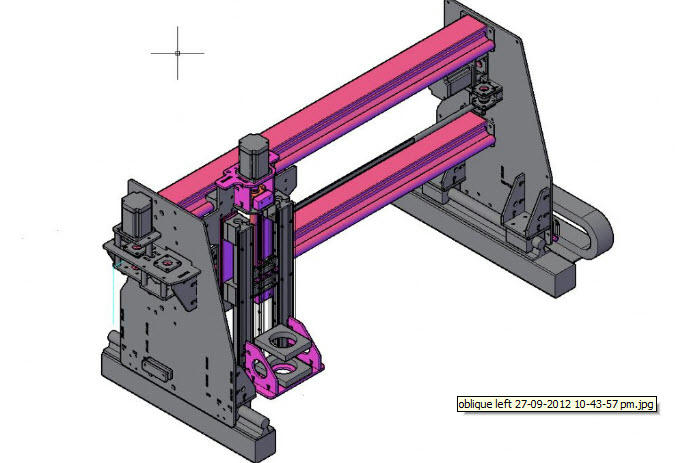
It was designed using Autocad in 3D a commercial program however there are many free CAD packages that can generate DXF files to give to a laser cutting service.
Almost No Welding? The design uses a joint design that is effectively (two) mortise and tenon pairs together with standard fasteners between the pairs, to make each connection) ; in this case M5 high tensile nuts and bolts, to join the various members together. Using this method there are zero sheer (well almost) forces on the fastenings only tension forces. I believe it could easily be scaled up to at least 12mm plate. Laser cutting has very little undercut; however there is some so plates will not ne perpendicular to each other and need to be supported in two planes to counter this. make sure the attached plates are interlocked in sets of 3 opposed at 90 degrees. Buy doing this using my best More and Wright square to test the joints I could see no light. bolt holes aligned so perfectly that there was no eye observable misalignment. There are no tapped holes in the plates. The bolts and nuts fit in slots you can see the slots in the views.
If you are wondering the only welds are the end plates of the 75mm sq tube rail supports, We are going to make a new machine with joined 5mm plate instead of these tubes. It will be more accurate and lessen the packing we needed to set the rails true on the RHS (we used a surface plate).
Laser cutting is now a fairly competitive area and the group was able to negotiate a reasonable cost for the work roughly steel cost plus steel cost x 2 for labour. The machin positioning accuracy was .01mm. we allowed on top of that .1mm (point one) clearance for the joints and no allowance for holes.
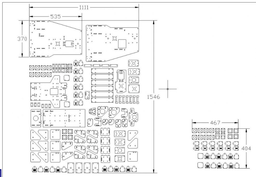
When the parts came back from the cutting service there were small (tiny) dags here and there. about 4 hours work total with a small file to clean all the joints and it went together like a clock. No welding distortion...... We redrilled all the round 5mm holes to clean them out as they were already laser cut it only took a few seconds per hole. the holes were positioned far better than I can do with a centre punch. Yes the machine could have been made by hand methods but have a look at the parts photo. how many hundred man hours. I have spent a fair number of hours just turning all the rotating parts .
The machine also uses Chinese round shaft linear rails and a z axis ball screw. You will be amazed how the cost of these have fallen on EBay and the like. X and y drives are 5mm timing belt.
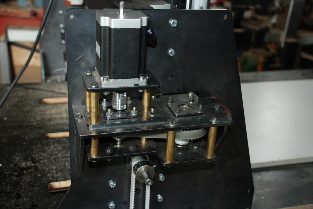
All the rotating parts use flanged ball bearings 8mm and 12mm again the internet provided a source ...VXB Bearings were very helpful and are a good starting point. The flange is clamped between the frame and a laser cut plate with 4 M4 bolts
The design is a collaboration with a great friend Leo S and The Bright Men's shed group, Bright is a central Victorian country town. A Men's Shed is a community supported building equipped with various metalworking, welding and wood working machinery; members pay a nominal fee to pay for tea and coffee. and are free to use the equipment (after doing OH&S induction and training).
Ther result is very pleasing indeed. clean accurate cutting.
We are now working on a new design 2400 x 1200 x 150h work area using the same methodology.
Cheers
John McNamara
Images and video below........
Cad Design:

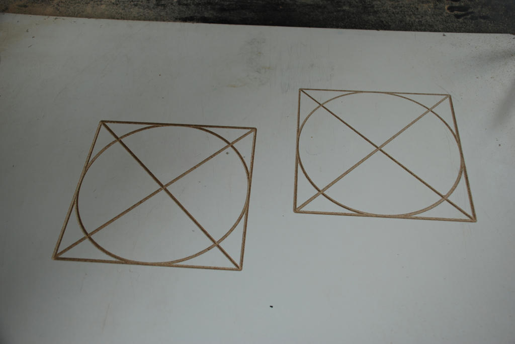
Laser file:

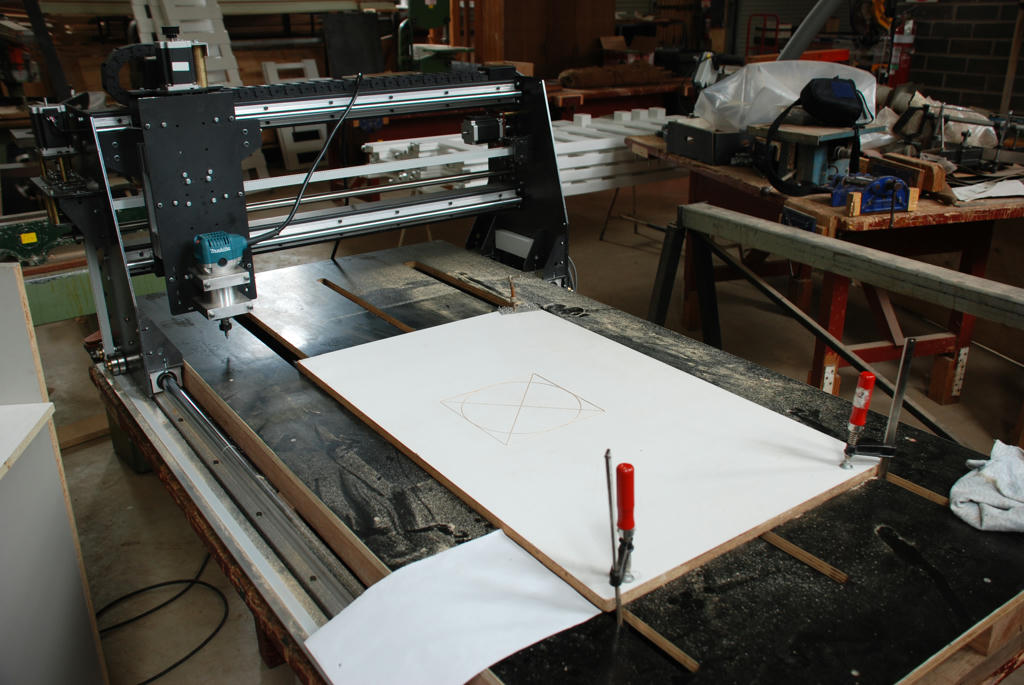
Overview (Table is temporary)

Every rotating element runs in flanged or circlip type ball bearings (clamped in laser cut holes)

A couple of movies....
The first test 120 mb file:
http://www.mediafire.com/?3atxyt94f76xk7cA bigger test 500mb file:
http://www.mediafire.com/?6yeg2c78d3vwivp