Hello Guest it is April 24, 2024, 05:29:37 PM

Show Posts

This section allows you to view all posts made by this member. Note that you can only see posts made in areas you currently have access to.


Messages - simpson36

961

You are completely backwards on this (I am only speaking towards an E-Stop circuit here). Your E-Stop circuit should be able to function independently of Mach and any other control/circuit board. The E-Stop HAS TO function even when the control fail (including Mach and/or PC).

For example: on my STDR-4C drive box the E-Stop kills AC to the power supply and consequently the G540 drive. So the motors stop, there is no power present to move them and the G540 stops thereby signaling Mach that something is wrong (external E-Stop). The E-Stop in Mach is only a signal to let Mach know that an E-Stop occurred Mach is not or should not be depended upon for E-Stop purposes.

I don't know what you mean by 'backward'. Clearly I am talking about servos  . . but you respond using a stepper controller for your argument, so you are not addressing the topic, or you do not understand it. Steppers are open loop so there is no equivalence to my comments on the usefulness of the circuit board at issue.

Perhaps you have a narrow definition of e-stop, but  you have not provided any more useful info than in your first post, so it is not possible to debate the issue. Blanket statements without any explanation, facts or details is not useful. You are just stating your unsupported opinion as if it was fact. To make a useful conversation, you would need to provide, as a minimum, the following:

1) define what you mean by e-stop.
2) what triggeres your e-stop? If a servo drive faults, what mechanism do you prefer to stop all movement and shut off the spindle?
3) if your DC stops as soon as you kill AC power, it would seem your PS is not designed properly as it should have large capacitors.
4) You state that killing the AC power to the controller is the correct way to stop the stepping action, but you do not explain why a catastophic problem with MACH, like a software crash, which would accomplish exactly the same thing, is unacceptable.
5) presumably you are aware that even if killing the AC would instantly remove power from a DC servo motor, that could actually CAUSE destruction because the servo drives would then have no way to stop the motors and they could easly coast into mechanical stops.
6) in your scenario, what is the purpose of 'informing' MACH of your external e-stop. To what end?


 

962
General Mach Discussion / Re: Problems threading on the lathe
« on: September 28, 2009, 03:11:44 AM »
Rich,

Seems to me the solution is an encoder on the spindle motor and a servo drive. An encoder can be put on just about anything.

The servo drive automatically does all of the stuff MACH is thus far been unsuccessful doing, i.e. compensatng for the motor slow down under load.

I can cut any thread with my 4th axis including tapered NPT and re-cut the same thread over and over with perfect registration.

This scheme would also allow a drill, small milling head or engraving spindle to be mounted on the cross slide for additional machining capabilities.

What would really be slick would be to take an X2 head and column and mount it on a slide behind the lathe. Bada-bing! Mini-Machining center II !

Downside, of course, is cost.


963
When I see multiple outputs from a circuit board labeled E-Stop warning sirens go off in my head. The purpose of setting Mach up with an E-Stop input is to let it know when an E-Stop occurs, but this is an auxiliary function. The E-Stop circuit however is its own animal and should not depend on Mach know an E-Stop occurred for all motion to stop (power removed from drives) A proper E-Stop circuit should no depend on any single IC on any circuit board for proper operation.

This is equivalent to the argument that one should not own a gun because guns kill people. The circuit is just a tool. It can be used in any way the user chooses. As I mentioned, the specific purpose is simply to amplify a signal and/or to  take a variety of different signal levels and voltages as input.

Servo drives have error lines that communicate operational problems. This little circuit simply takes that error signal and amplifies it for reliability and as a bonus, allows the user to have remote LEDs to easily monitor what's going on. The chip has enough pins to handle two drives. Those drives would be in the system anyway and would have error lines, so the circuit board does not 'add' anything new nor eliminate any options relative to the preferred e-stop scheme.

It also would provide a convenient means to run a higher voltage on limit switches. Presumably your e-stop scheme uses limit switches? There are undoubtedly a dozen other possible uses for this little guy having nothint to do with e-stop.

Setting up an e-stop scheme outside of MACH makes no sense to me for many reasons.  Occasionally I read posts about this concept, invariably presented only as a vague reference (as you have also done), but so far I have never seen anyone provide specifics on the how and why of this theory. I would be most interested in an explanation.

964
Thanks!

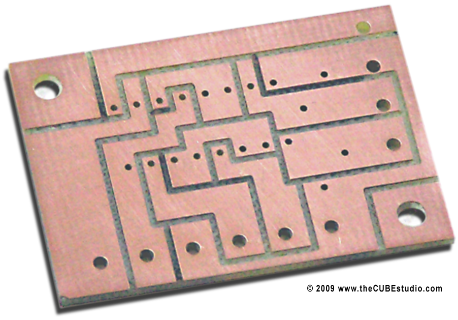
Here is the G-code to route the board for anyone so inclined. Ignore the speed on the first two files. I used 28k RPM die grinder mounted on the mill head for the 1/32" end mill. The 1/16" end mill for the second two did run at 7K in the machine spindle (max speed), but would be better run at routing speed if you have a way to hold it.  

If you want to rout and drill each size with the same endmill, you can combine the first two and the last two files.

http://thecubestudio.com/CNCdrive/ErrorLinePCBtrace.tap
http://thecubestudio.com/CNCdrive/ErrorLinePCBdrillSmall.tap
http://thecubestudio.com/CNCdrive/ErrorLinePCBdrillBig.tap
http://thecubestudio.com/CNCdrive/ErrorLinePCBCutOUT.tap


965
Another update on the Rutex drive failure:

I received an e-mail responce from Tom Eldridge,  not as as a result of my official contacts, but as as result of posting here in the Mach forum.

He states in part: "When a customer asks for warranty service, I normally send out the replacement the day I receive the bad drive from them.  If I am comfortable with the customer, I will send out a replacement if they call me right away, even without payment and even before I receive the blown drive.  If you had called me right away, I'd have done that for you too. "

Note: This statement is consistent with reports I read and obtained from Rutex users, as noted in the review. I did not call Rutex. I used only e-mail communication.

Mr. Eldridge goes on to add this condition to the warranty offer: "Normally I would just warranty this for you, but if you put the current setting higher than I recommended and if the drive solder runs are damaged he may only want to warranty them half way...in other words, you would have to pay for half of a drive to receive a new one from us."

Note: The drive is rated at 20A. The recommended setting above which the warranty is cut in half is 7A. This reccommendation, to my knowledge is 'published' only in a single old posting in an obscure Yahoo forum. The drive continues to be rated at 20A in the product literature.

Thus I have apparently voided my full warranty not by attempting to repair the drive, but by using it at it's rated capacity. Fortunately, I have successfully repaired the drive myself, but as others have done, I  will have to 'derate' it and find an use that requires only 7A max.

966
Update:

I reported the drive burn-out and asked for information about repair on both the Rutex web site and after getting no response, there, also by email directly to Ton Eldridge, the Rutex rep. Thus far no response their either.

An interesting discovery that I made while researching the parts needed for repair, is that the MOSFET controller is an obsolete part. One of these controllers is burned out on the drive along with the MOSFETS.  Mouser has no stock and Newark says that after their stock is gone, there will be no more available. Neither of these major suppliers lists a replacement or equivalent part.

The controller is an ST brand L6386. It would seem there are two conclusions to draw:

1) the well known Rutex 'burn out ' issue is NOT confined to older models or even a single current model

2) it seems reasonable to assume that even the current model drives will soon be unrepairable for lack of available parts once the obsolete stock is used up.
 

967
Well, wonder of wonders, here is my first circuit design and prototype electronic thingy  ;D

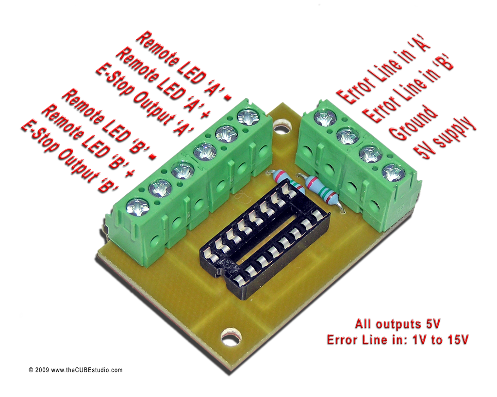
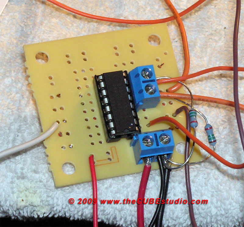
With guidance from tech support at CNCdrive, I was able to figure out this circuit. This was created to take care of the weak error line signal from the CDCdrives products, but it will take even a very weak signal anywhere from about 3V to 15V and put out multiple strong 5V signals to drive a remote LED and even a stubborn BOB with hungry optoisolators.
This circuit solves, for example, a specific problem discussed here not long ago. A solution to noise causing false e-stops on limit switch or other e-stop lines is to increase the voltage to 12V, however, that creates the problem of interfacing that back to the 5V BOB. This circuit solves that problem. The 12V line from the limit switch goes into the Error Line pin and the 5V out goes to the BOB.

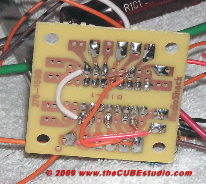
First I made a prototype with a Radio Shack proto board. Schematic has been added here - scroll down to chapter 5.5:
http://www.cncdrive.com/datasheets/Dugong_manual.pdf

This is the top and bottom of the first prototype:


After the circuit was tested and working, I went on to design and rout a custom PC board and put it all together. I have purchased the SMD version of the chip in case a wave of motivation overtakes me (unlikely any time soon).

Here is the routed PC board:  1/32" end mill 28K rpm and 1/16" endmill at 7K RPM.

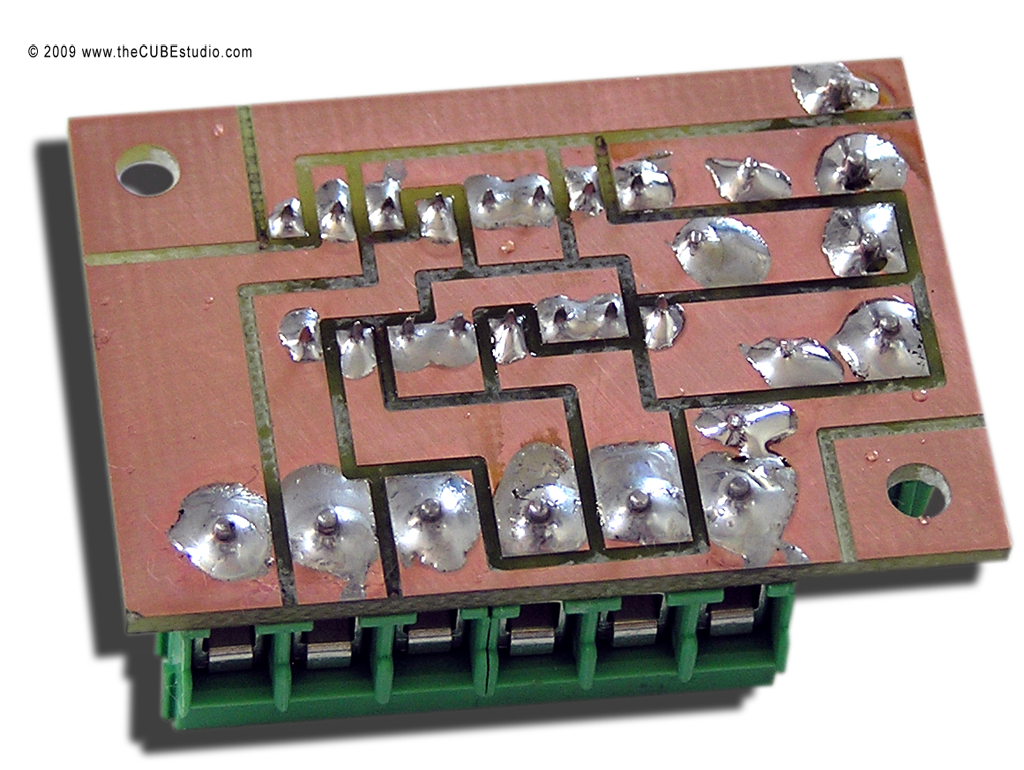
And top and bottom views of the completed part. . . less IC chip. . and prior to cleaning up the rosin:


968
Interesting develpoment . . .  the Rutex self destructed.

Unlike the Whale  .  which I murdered with my own mistake, the Rutex just exploded for no particular reason. In the process, the PS rectifier was also fried.

The AC line-in fuse on my PS popped off and I was able to track it down to one of the bridge restifiers being shorted. Once I located the problem it was relatively simple to replace. However, on power up, the Rutex oddly was moving the motor continuously in one direction.

I reset the drive and zeroed the encoder and turned the HV back on and  . .  POP!  Fire and smoke from under the Rutex . . . . and . . . the rectifier was fried again. Hard to say who threw the first punch.

The Rutex exploded a MOSFET and has thus far resisted all attempt at repair.

Each drive has an independent fuse on the positive DC power (20A in the case of the Rutex). Despite the exploded MOSFET and the shorted Rectifier, that fuse did not open. I replaced the rectifier again and the mill is back running fine with the two CNCdrive servo drives and a stepper back on the Z axis for now.

I don't know if this is enough info for anyone to formulate a theory about what happened. What I don't understand about the event is how the Rutex somehow *appears* to have fried the rectifier. Is that possible?
 

969
General Mach Discussion / Re: Going back to Iraq, see ya fellas.......
« on: September 20, 2009, 02:45:55 AM »
Let me first express my a sincere appreciation for your service, and all those who protect us.

Stay away from things that go boom.

To all fighting men and women . .  Come back safe!

And to the rest of us . . . welcome them home.

970
Do a search on this forum. I posted the card and the exact drivers you need to work with MACH, and how to set it up.