Hello Guest it is April 25, 2024, 09:37:49 AM

Show Posts

This section allows you to view all posts made by this member. Note that you can only see posts made in areas you currently have access to.


Messages - simpson36

951
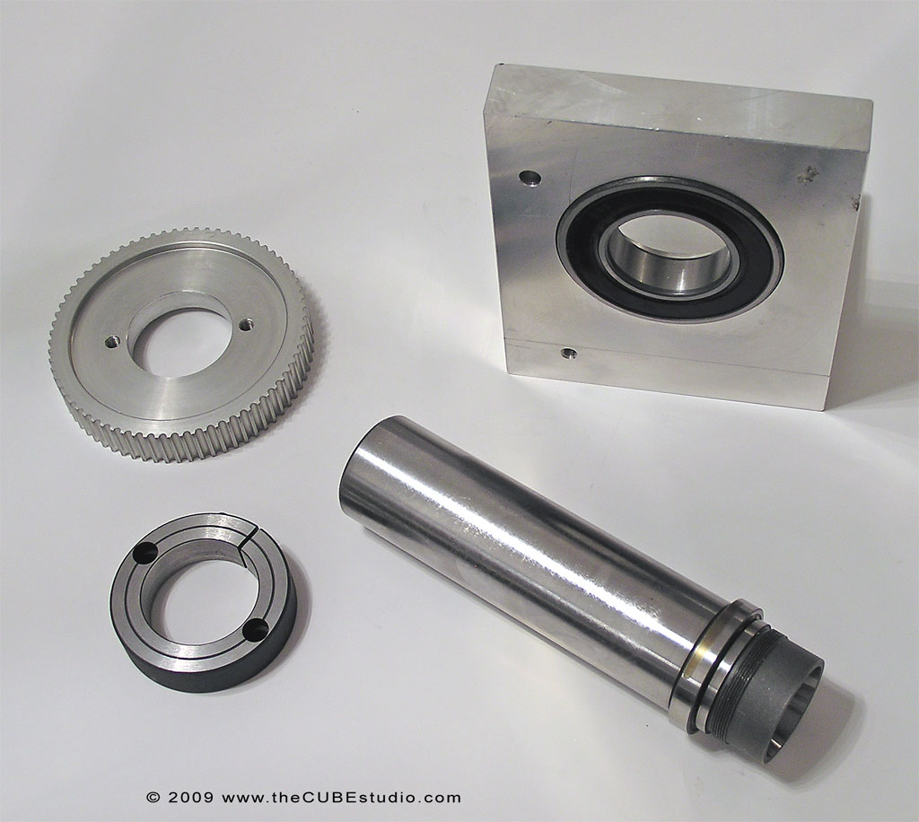
These are the new drive parts. Older trapezoid tooth belt is gone, replaced by newer GT2 type. Quieter and can handle a lot more power. This time rather than making a pulley from scratch, I took an off-the-shelf pulley and modified it by cutting out the center and mounting it to a stock clamping collar which is comes already drilled for mounting a pulley. Between the stock pulley and clamp collar, I saved several hours over starting from scratch. Collar is bored for a slip fit on the spindle . . no  more threads. Preload will be accomplished differently. More on that later:

Spindle is out of a PhaseII brand 5C spin indexer. Still an import, but about three times as expensive as the normal junk and it is much better quality. Roughness in center portion of the spindle is from me reducing the dia slightly in that area with a coarse zirconia flap wheel to ease bearing press and reduce the interference fit on the rear bearing for preload purposes. Front bearing (next to shoulder will have full press fit. I will probably be making my own spindle, but for now this is easier.


952
UPDATE: started new prototype. Again not doing anything exotic so anyone wanting to follow along should be able to duplicate these results and build yourself a nice addition to your mill. Material is 1" thick 6061 plate. Motor plate was planned as 3/8" thick. but is 1/2" due to 'scrap on hand' material sourcing.  :-[

This is the new frame  . . essentially the same as the first proto, just bigger to allow for larger chuck or workpiece. Also better fit to larger table on my planned next mill. What is very different is the motor mount. Expensive idler is gone and belt tension is now accomplished by rotating the entire mount. The big hole in the mount is not necessary. I put that in to ease belt and pulley changing if I want to experiment with different ratios. Currently 2.5:1 which is a compromise from previous 4th axis which had both 2:1 and 3:1 ratios.


953
I was doing some ad-hoc edits at the mill computer na dwishing I had a reference guide so I logged on here to check progress.

Needless to say . . . I am one happy camper!!   :-* :-* :-*

954
I've had this same issue after a feedhold. I use G95 and no spindle sync.

It is rare that I use feedhold witout following up with a stop, so it was not something that I dug into for a solution. I *think* I am using rev .028 on the mill,, but I would have to check to be sure.

955
General Mach Discussion / Re: Problems threading on the lathe
« on: October 05, 2009, 04:27:38 AM »
Now we start the movement, since we're in mm/rev mode, we know the mm's of motion were calculated based on 24,000,000 clock cycles per rotation. If the ortation is sensed to be now 2700,000 clocks per rotation, we know the spindle has slowed by 12.5% .. so we now slow the output during the next rotation by 12.5%, and keep track of this rotation.

I pondered this proceedure when Art originally posted it, but a pitch error INCREASE would not be consistent with the above quoted correction proceedure, so it was an unresolvable quandry. Now that Rich has discovered that the pitch is DECREASING, it makes sense.

Therefor, I can submit a possible solution . . .  hopefully.

Taking the above quoted proceedure as literal and accurate, a correction of only 100% of the previous rotation error is not adequate. While the error would removed from subsequent rotations, the original measured error remains. Also, as stated elsewhere by Art, the process begins anew with each pass. So absent historical data being brought forward, this remaining error would naturally accumulate.

My suggestion for a solution to this issue is simply to make the correction in a subsequent pass in an amount that will not only eliminate the error in the current pass, but ALSO make the correction for the error measured in the previous rotation, which is still present in the thread at the begining of the 'correction' rotation. Only this combined correction would result in restoring the correct relationship at the end of the adjutment event.

A simplistic example would be that the measured error is 5. If the next rotatation compenstaes by 5, as described in the quoted passage, then the overall thread progress still contains the original error, which will be carried thru the entire pass, and then be componded by the same process occurring anew because the next iteration is blind to the previous data.

It seems to me that adding a correction for the previous (measured) rotation to the calculated correction for the current rotation is the missing link.


956
General Mach Discussion / Re: Problems threading on the lathe
« on: September 28, 2009, 02:36:03 PM »
Threading solutions for the 'stab-in-the-dark' department:

Here are just some thoughts that occurred to me in noodling over the MACH single point threading challenge. These ideas may or may not improve success, (my dime says they will), but they cannot do any harm and are free to try. Hopefully they will prove useful:

1) arrange for the tool entry point to be as close the the index pulse as possible.

2) use a more sophisticated threading technique that will even out the load from one pass to the next.
       Alter the G-code to cut only one side of the thread and reduce the feed (or depth of cut if messing with feed confuses the adjustment algorithm) such that as successive cuts take more 'height' of the the thread, a  corresponding reduction in depth or feed equalized (within reason) the power required for the cut.

3) use a motor speed controller based on PWM rather that SRC and use one that has good compensation for slowdown. I am using a Minarik drive which has an adjustment for that and does a very good job trying to maintain set speed. Certainly there are others that also work well.


If MACH has less total change and less delta throughout the cut, then as the function was described to me, it *should* be able to zero in on an optimal correction sooner and maintain the correction thru successive passes.


957
General Mach Discussion / Re: Problems threading on the lathe
« on: September 28, 2009, 02:23:49 PM »
I'll address this to Art and Rich both as combining the info implies that the effort is aimed, at least somewhat, at marginally powered hobby lathes. Correct me if that is not the case.

Thank you, ART for the explanation of the function. This is quite a fascinating topic. I see that the new method for measuring is more accurate perhaps, and even if the 'bell curve' could be considered a prediction of sorts, the problem remains that it is after the fact and only once per revolution. And there are additional factors conspiring against the perfect thread.

Measuring the period of a full revolution injects another assumption into the equation. Not only must you assume that slowdown will be statistically similar for the next revolution, with only one pulse per rev, you also must assume that the slowdown is consistent over the entire revolution. I think that is unlikely, especially if the tool entry azimuth does not coincide closely with the pulse azimuth.

For example, if the tool enters at 180 degrees relative to the pulse, your measured revolution will 'see' only half of the slowdown, and therefor misadjust by 50% the needed correction for the next full revolution, and will consider the increase in the subsequent time period as a further slowdown and misadjust again, followed by another change in period, and so on . . . . . if I am thinking correctly.  Additionally, it is my impression that forum members here (as well as the available wizards, perhaps?) do single point by a simple plunge with equal depth of cut for each pass. If that is correct, then each pass will require more power and there will be a corresponding increase in the slowdown from pass to pass. This presents a vexing problem that there is no solution for so long as a single pulse per rev is used.

This brings up an interesting question of harmonics . .  if you will. It is possible that the 'oscillation' in speed correction described above could be self exciting? That would explain the escalation of the error as the thread becomes longer . . as has been described here and there.  I have not followed this closely so I'm shooting from the hip here.  :P I have not thought this through at all . . just a mad thought. 


958
I have designed/installed countless automated industrial systems: I do know what I am talking about. I have limited this discussion to E-Stop as it was the point I first brought up. I am not picking a fight with you, just stating that a circuit like this is not proper to be placed in an emergency stop chain.

First FYI, I enjoy a good fight, so long as it is a debate with facts and not an argument with emotions. Second, if I though you didn't know what you were talking about, I would not waste my time discussing anything with you at all, so please consider that. I'm hoping there is something for me to learn here . . . if I can drag it out of you . . ;)

There are two talking points here. One is the methodology of your e-stop scheme. I do not agree with the little bit you have detailed, but I agree that it is a large subject not suitable for a hijack of a much simpler thread topic.

So, to confine my response only to the portion of you statement that I have quoted, you still have not spoken at all to your continued contention that the simple circuit is 'not proper' in an e-stop scheme. The circuit does nothing but take a weak signal, one not designed to drive an optoisolator for example, and boosts it to a full solid 5V signal. It does not create a signal, nor block the signal, nor interpret or change the signal in any way. There is simply no way this can have any negative effect on any e-stop scheme you devise.

You have talked around this, but not address it specifically. Can you specify how an amplifier on an error line can in any way effect whatever you, I or Joe down the street considers to be the optimal e-stop arrangement?


959
General Mach Discussion / Re: Problems threading on the lathe
« on: September 28, 2009, 11:41:20 AM »
Rich,

Just a comment on your driver test result. The period of time that your pulse goes slow seems massive. I have never had any more than the width of perhaps a single pixel above or below that line, even at 100k.

It would be interesting to calculate the number of pulses effected during the duration of the disturbance

960
General Mach Discussion / Re: Problems threading on the lathe
« on: September 28, 2009, 11:29:52 AM »
Perhaps I am missing something, but I see no way that any software can compensate for spindle speed using a single index pulse per rev. It is a physical impossibility no matter how fast the computer or the software is. These are the inescapable conditions that immediately occur to me;

1) No matter how many pulses per rev, the data is always after-the-fact, in other words, for a slowdown to be detected, it must have ALREADY occurred, so it is too late to compensate for deviations between the detection read and the previous read. Unless the delta in time and error is very tiny, AND the mechanical system response is extremely fast, then a correction, (which can only be done as a 'catch-up' unless some type of prediction is made), really looks to me to be undoable.

2) If the spindle motor slows down significantly, then it is a given that the drive motor has insufficient torque to maintain RPM. It would be illogical to presume that the already overloaded motor would have any available excess torque capacity to catch up with the now over advanced threading feed, so the only alternative would be to slow down the feed, which in turn would change the load on the motor since this action would change the effective depth of cut from the last pass in that portion of the thread where the correction is made.

I do not know how MACH attempts to keep the threading synchronized, but it seems to me that it is irrelevant because if my thinking it correct, there are not adequate data for one method and inadequate power in the other.

It occurs to me that only a very high number of samples per rev would have any chance of maintaining sync and then *perhaps* only if MACH had data on how many amps the motor is drawing during the cut.

The fact that people with very high power spindles (relative to the size thread being cut) have no problems tends to support my conclusion, but again, I may have missed something.