Hello Guest it is April 18, 2024, 01:56:22 PM

Show Posts

This section allows you to view all posts made by this member. Note that you can only see posts made in areas you currently have access to.


Messages - simpson36

771
General Mach Discussion / Re: how to control z-axis brake
« on: June 04, 2010, 11:50:39 AM »
forget the servo....
my problem is using step and hope system can auto release before z moving and lock when z stop....
z-axis using stepper..

In this case, have nothing new to add to my previous comments.  I was not aware that steppers had electronic brakes . . . .  live and learn.

772
General Mach Discussion / Re: how to control z-axis brake
« on: June 04, 2010, 11:11:13 AM »
the part that I ever use brake on servo motor system is reply the position error for braking and servo motor active, my solution is reduce the PID so that system can hold by motor and brake together...
of course I can put M code for release brake in my process, but my stepper will lose pulse, that is why I want to know if there is a way to auto release the brake.

I'm afraid I don't understand what you are saying here. Also it seems you are using the terms 'servo motor' and 'stepper' interchangeably, which is not helpful.

773
General Mach Discussion / Re: how to control z-axis brake
« on: June 04, 2010, 07:45:06 AM »
I ever use the brake on servo motor system when the servo is still clamp, but i decrease the gain of PID control first....

OK..my point is using the brake to help my stepper holding the position....any good idea?
and why GetDRO(16002) always return "0"??

From the department of redundancy department:
If you are going to go into MACH to get variables, then you have already coupled your process specifically to MACH, so why not just write a macro to engage the brake and add that to the G-code between moves (with delays if needed). That is how I implemented the 4th axis spindle lock initially and it worked fine.

My quest for an autonomous function stems only from the goal to make the operation transparent to MACH, or more broadly, to any CNC controller.

Note that I am simply commenting on your question, not endorsing any particular idea.


774
General Mach Discussion / Re: how to control z-axis brake
« on: June 04, 2010, 07:32:49 AM »
. . . and the motor is clamped and left active, the current will climb in order to attempt to position the motor within the specified following error if any occurs.
This is a function of the servo drive, and as I pointed out, some drives have the ability to automatically engage limits during the condition you describe. Some even allow you to set the range in encoder counts within which this limit is applied.

You cannot guarantee that positioning a servo to a certain position and then braking it that there will not be any servo error occur at any point.
Actually, you can. Again it depends on the servo drive you are using.

I understand the thought process that ends in "do not restrain an active servo motor", but while this advice was valid, I am finding that it is no longer universally applicable. An analogy would be the advice to 'pump your brakes when you are driving on ice' which was of course valid and taught in any driving class . . . until anti-lock brakes came along. I discover that there are some clever people out there designing servo drives that have actually though about this topic and built some interesting features into the drives. Not all drives mind you, but some. There are still a lot of cars on the road without anti lock brakes also, so 'pump the brakes' is still good advice, but not in all cases . . since pumping anti lock brakes is a decidedly bad idea.


[/quote]

775
General Mach Discussion / Re: how to control z-axis brake
« on: June 03, 2010, 06:31:19 PM »
I agree that a counterbalance is a better solution for a typical Z axis, not only to reduce stress on the motor, but to eliminate backlash . . a benefit unique to the Z axis.

On the other hand, I disagree that a drive motor 'must' be deactivated prior to an axis being locked in all cases. I have been doing some research into this question and I find that there are many different applications and each has it's own set of variables to consider. I am wokring with a servo drive that already has a separate set of parameters that are automatically engaged whenever the motor is not moving, so manually disabling the motor *might* be superfluous (too early to tell just yet). I know of several stepper motor drives that automatically reduce power when the motor is not moving, so locking an axis in that situation would do nothing but prevent stress on the motors and potentially prevent lost steps in the case of an extreme force such as occurs during tool chatter while the motor is at reduced power.

Then there is the example of a rotary tool holder where it is evident that the motor is used only for positioning and a positive mechanical lock takes the cutting forces.

Axis locking is an interesting elephant, to be sure. 

776
General Mach Discussion / Re: how to control z-axis brake
« on: June 03, 2010, 11:08:58 AM »
I still need one way to realize the software function, to solve the problem or to prove his solution fail
Can anyone tell me the way to get the "togo" var of Z-Axis?

I am wokring on a similar project, but for the A axis. My goal however, is to make the operation tansparent to MACH.

My current thinking is to use a 'position reached' output on a servo drive to activate a brake. That seems promising, but I have not had a chance to develop the idea yet. I am busy with other stuff at the moment, so it may be a while till I revisit this project.

777
AC servos have a continuous rating and an intermittent rating.
AC Servos (or DC Brushless, same thing ;)  ) have their windings in the casing  of the motor which means they are very efficient at dissipating the heat.

Good point, Hood. I should have mentioned that the motor that was asked about is a DC brush motor. It has continuous 7.6A and max 38A. This motor is Keling and they provide only minimal information on their motors. Higher end DC brush motors provide more information about how long the motor can be at max amps or how hot is is allowed to get without damage. I have a DC brushless motor to play with but it is far too small for the spindle. Perhaps I should consider and AC servo motor for the spindle.

778
I think you use servo motor for Spindle.
Constantly moving, does not hurt to Servo motor?
Servo motors do have a duty cycle and are expected to have 'rest' time and therefor have no provision for cooling. Running constantly might cause heat build up in the motor. The motor is rated 6,000 RPM and I have had no problems thus far running continuously at about 4,000 (a guess) with the mill on 'low range' if you will. On high range, at 7,000 RPM, both the spindle and the motor get hot after a while. On my previous X2 mill I ran 7,500 RPM for long periods and had an aluminum finned block on the side of the head to draw off the head. The spindle motor of the X2 has active cooling and it got hot, but not overly so. 

In my application I do not plan to run the spindle at high speeds for more than 10 minutes or so at a time, so it is not a priority to investigate that. If I do need to run at the MAX 8,500 design speed for extended periods, I would need to add cooling to both the motor and spindle lower bearing. The lower bearing is currently pressed into a 1" thick block of aluminum which dissipates the bearing heat quite well enough for what I am currently doing.

Active cooling would be relatively easy to add.

779
Look for shared interrupts between the USB and IDE, Graphics card, SCSI, etc.

I run g-code off a thumb drive no problem and have a USB mouse as well.

780
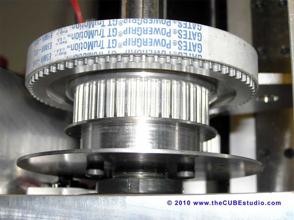
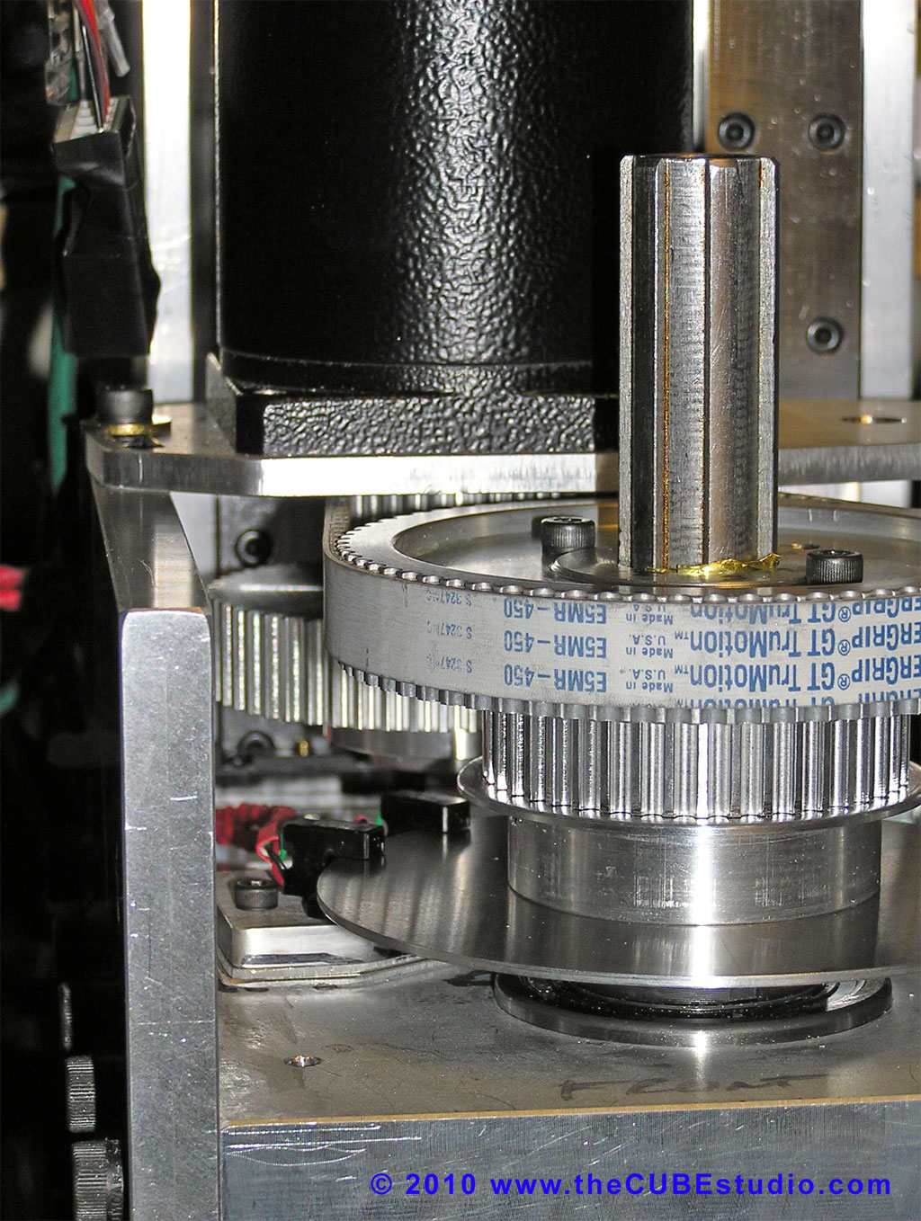
The mill is not completed yet in the photo. I later added way covers and finished the drive belts, added the spidle brake, etc. The spindle has two ranges 0 - 3,600 and 0 - 8,500

The bearings are not fully broken in yet, but I have had the spndle a bit over 7,000 RPM so far running the motor from a 10A 120V variable speed controller. The spindle is smooth enough at most speeds, but there are some 'illegal' speeds where harmonics come in. I am building a dynamc balancer now that hopefully will allow me to smooth it out more. 

When I was running the motor with a servo drive, I tapped 3/8 - 16 in aluminum. I don't know the limit yet.

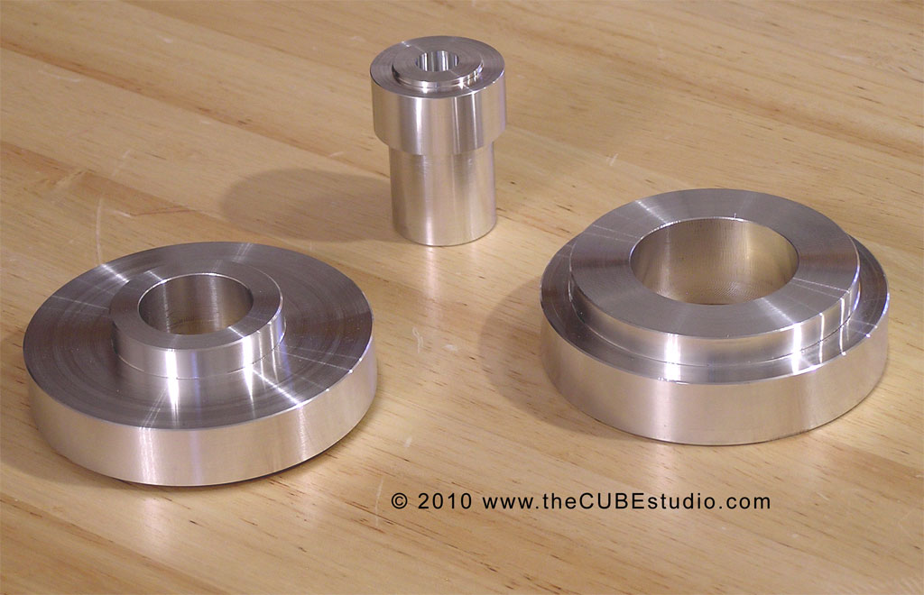
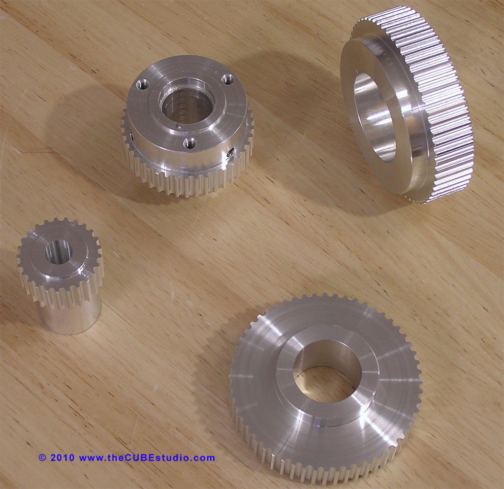
Here are some pics of the drive development: