Hello Guest it is April 26, 2024, 01:37:11 PM

Show Posts

This section allows you to view all posts made by this member. Note that you can only see posts made in areas you currently have access to.


Messages - simpson36

571
Just finished another (unrelated) project and I am back on the BT30 spindle. Carving has begun on the turkey. The part is currently flipped over and I am working on the nose, which includes the nose beargin pad, the BT30 taper and threads on the nose for a bearing retainer.  Next is another flip and a steady rest for boring the 8.5" deep hole to final size. Then grinding the bearing pads to complete. The BT30 taper will be final ground in-place on the completed spindle.


Progress photos:

Initial OD turn including body,  top bearing pad and drive end.


And now drilling hard material 1" diameter 8.5" deep. The operation stalled the previous 'Super Duty' 4th axis and it had to be done in three steps. That was one of the motivations to create the new 'Mega Duty' 4th axis. The previous 4th axis could do the job with a bigger motor, but 750watt is the largest motor Mitsu makes that runs on single phase power. The new 4th axis munched thru this operation with no problem. Coolant fed drill. No pilot hole.


572
NEW VIDEO!!

Hood: Thanks!  Now it makes sense. Very clever use of available features -  as usual.

Dan: the amount of play in the gears did not make a noticeable difference in the tapped threads. The tap went in and out smoothly, no binding, no aftercutting, and the screw feels (I know this is subjective) the same as threads tapped in the mill spindle. Check it out.

http://www.youtube.com/watch?v=Dd_M6Li_OrA&feature=youtu.be


573
My drives can be set up to roll over at any amount of encoder counts, it is in fact the way I use it for my lathes turret, it has a 20:1 gearbox on the motor so the drive is set up to roll over at 160,000 pulses. As the drive is also an indexing drive I can set up up to 64 positions and call any one of them from a combination of 6 inputs, life is easy :)
Can you explain the relationship between the gearbox ratio and the rollover point. I've noodled over this on and off for a while now and it is not coming clear. I'm sure it is one of those obvious things that somehow become invisible if you think about it too hard.  :-[

Quote
Big problem you have is you are trying to design in safety features and  you have no control over the hardware it is going to be fitted to. I think likely the best you are going to manage is to have a setup that requires certain signals and leave it up to the user to provide them whether that be by real signals or trickery. Either way you have done your best to make things safe and it will be the end user that has failed if they dont do as needed.

Well, you hit the nail on the head, Mr. Hood. I already have some trouble with people modifying stuff in unsafe ways. I've been asked already for the design, including buying it, by some folks who are well known around here, but I have not shared anything other than what is in this thread. I  am a bit paranoid about liability because I live in the USA where people successfully sue because the coffee was too hot and burned them when they spilled it in their lap while driving . . . . absurd, but true. The more I contemplate your statement, the more I lean toward keeping this exclusively for my own use.

574
Like your solution! Especially the fact it turned out relatively inexpensive. There are such heads ready available, but are very expensive.
I think you are talking about the right angle gearbox? I don't know of any that would fit onto an X3 spindle, but you're right, the Bridgeport angle heads are a bit pricey. An interesting advantage of mine is that I still have the vertical spindle active while the horizontal is running, so given enough space, I could still have the mill spindle participating in the machining process. I have two mounting schemes and will implement both, one is horizontal mounted behind the spindle and belt driven. This has the advantage of being strong and rigid and allowing different ratios.

The second scheme mounts the gearbox on the spindle (ala Bridgeport) but actually bolts to a collar that in turn bolts to the bottom of the head. Advantage here is that the drill can now be rotated to any position in the horizontal plane. Disadvantages are that it consumes the spindle, interferes with the tooling bar and is a relatively weak mount because the stress has to run all the way thru the aluminum gearbox casting.  Still, If I need angled holes, I can make them.

Quote

By the way, don't see a reason for preloading the bearings if all it's going to is drilling. I think there would be much more backlash in the gears that could be a problem for rigid tapping.

Dan

Can't have the shaft flopping around if I expect to hard tap or do any light milling. The gear lash is a good point. Had no occurred to me yet.  On first blush, it seems I could measure the backlash and compensate in the tapping macro. Worst case is I would get a bit more H than is built into the tap. For most applications, this would not be an issue.  We shall see. I have to get it mounted first and then work out any  . . .  um . . .  less than optimal characteristics . . . that may arise.

575
OK now for the side trail. This is related to the BT30 spindle project because the device will end up inside the head of the new mill. For now, I have built the device and it will be installed under my current mill head.

Problem: need to drill bolt patterns in parts machined on the 4th axis. Taking the parts out and drilling the bolt pattern on the mill is a PIA, especially since the 4th axis has indexing capability and can easily rotate and hold any part for drilling. The mill had revolves and can face the 4th axis, but that is more time consuming than moving the part to the mill for drilling because the head has to be re trammed each time.

Solution: horizontal drilling spindle on (for now) or in (the new mill) the mill head.

To accomplish this, you first purchase one of these  - new:


The you grab one of these off Ebay for something less than the new price of US$285 plus something like $80 for the MT adapter. The chuck is the largest Jacobs 'Super Chuck' with capacity to 3/4". The huge MT adapter was trashed and unusable, but for my purposes, it was perfect because it was big enough to cut down to 20mm.


Next you reduce the diameter of the MT adapter to a 20mm press fit and duplicate the snap ring grooves and pin holes of the original shaft.

Move the bearings and gear over to the new shaft:


Rig a method to preload the bearings and reassemble. Now you have a horizontal drilling capability that can hold tools up to 3/4" and can drill and hard tap a workpiece held in the 4th axis. ONe of the first uses will be making the BT30 spindle housing.


576
Hood; thanks for all of the info. You are a little over my head with the last post which only shows that I have a lot of study to do yet on the best way to skin this cat.

I have a tiny update and a short side trail for this thread. First the update: I have decided to go the cartridge route and make a complete housing for the spindle. This solves some problems and creates some problems. It seems DIY prefer aluminum for the housing, but I prefer steel for a number of reasons. The problem is that a chunk of steel large enough to create a flange and hold the massive lower bearing AND long enough is over US$200 and heavy as hell so shipping is also scary. IN the photo below, are the raw materials that I will be turning into a spindle. Purchasing an appropriate size piece of stock for the nose and the body of the cartridge put the cost under US$50, but it introduces the problem of attaching the two pieces together. After weighing options, I have decided to furnace braze the two pieces together. I have a furnace large enough to hold the parts and I have acquired a furnace brazing paste that contains flux and metal powder which is applied ti a specific slip fit between the parts. I am well aware of the furnace brazing process, but have never done it myself, so this will be interesting. If anyone has experience with this process, please post any tips or tricks, or specs on the slip clearance if you know what it is. I know there is a spec, but have been unable to find it so far.


577
 It would be extremely unlikely for the encoder to happen to be in the correct position by chance, so  Degrees-off-of-index is needed to locate the actual desired home position relative to the random position of the physical encoder install, but I don't think it would be usefull in homing a spindle with reduction (other than the few ratios I cited).

For example, take a simple 3:1 reduction.

With the motor homed, the spindle could be at  0,120, or 240 degrees. Each position would require a different number of motor degrees to reach 0 (or 180) for a tool change, and I don't *think* the drive keeps track of encoder rolovers and even if it did, it would be a nightmare to extract that info . .  again that just 'on the hoof"  :P

Even with 1:1, 1:2, 2:1 etc, ratios, the degrees from index would still be useful to move the spindle from 'opto home' to the required tool change orientation. I think I have that feature on the Xenus, but now that you've brought it up and I've noodled over it a bit, I can see where it will be needed to operate the ATC from a PLC. I had to write some tracking code for my balancer and that encoder is absolute, so it was tolerable . .barely. I think I would prefer to get poked in the eye with a sharp stick to attempting that on a PLC with an incremental encoder. Kflop comes to mind because they have a lot of libraries. Perhaps I will take a peek at that.

What is clear is that this aspect of the process is going to need some more scrutiny.

Really I did not have an appreciation of how complex it would be to develop an ATC. Or more to the point a safe ATC. The mechanisms needed are only a small challenge, but the function will be a large one, methinks.  This is another of those cases where one of your random comments is going to probably save me a lot of headache down the road.  :-*

578
No surprise that your setup seems well thought out for a manual change power draw bar. Did you build it or did it come with?

Is your spindle motor a direct 1:1 drive or is there a reduction?

It seems to me that anything other than 1:1  1:2 or 2:1 would defeat the drive's homing as the spindle would stop at a random spot when the motor homed. My current temporary mill has odd ratios on the dual range head. I suppose they made sense at the time, but at this point  ???.  I will need to use the opto which is still there left over from tach duty quite some time ago.

For the new mill I am thinking about doing a 1:2 and 2:1 ratios for low and high. In this scheme, the motor can home on the encoder index and the tool will always be at the correct azimuth.  Those ratios would also provide a nice low range for big drills and big taps and about 7K max spindle speed.

How is the knee related to the ATC? Would you mount the tool holders on the table?

579
Ha ha now that is naughty, editing quotes ;D
The Devil made me do it!     Actually it was the spell checker and an itchy trigger finger. Why the spell checker looks at quotes is something of a mystery.

Quote

My PLC is a Koyo DL06 and I programme it with the graphical  ladder logic which I find very easy compared to script.
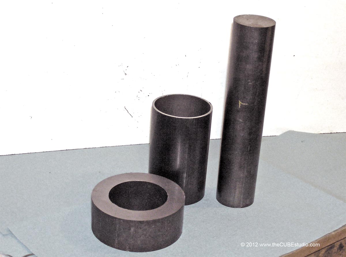
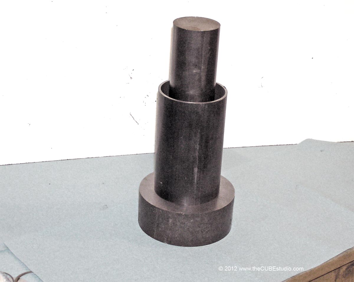
My solenoid can only act if the PLC is getting a zero speed signal from the spindle drive so it is partly hardware and partly software I suppose. Drive and PLC ladder being the software, drive output/plc input and relay output from the PLC being the hardware. I dont have it via Mach at all as I dont have an ATC so my drawbar is just via a button on the panel, that may change in the future if I get time to servo the knee or even better pick up a decent bedmill :)
This is the type of thing I am looking to protect against; accidentally hitting a button, MACH or the PC misbehaving. I have a pneumatic lock on both the 4th axis and the spindle and when things go awry, sometimes I hear the familiar 'pop pop' which is harmless in this case, but would not be if the 'pop' was the drawbar releasing a tool. I plan to have the interlocks that you have wisely included on your mill and also have  . . .  uh . . I'll call it a 'lock' to differentiate from 'enable'. The lock will be engaged at all times via spring load. This will be a mechanical interference which will physically prevent the cylinder from contacting the drawbar. It will have to be retracted vie electric solenoid before the drawbar can be released.

The sequence will probably be something like:
*receive tool change command from MACH (or manual override)
*wait for spindle to stop rotating
* - - - 'disable' - - drive. This is a topic in itself, and could be:
  - engage spindle lock, disable drive
      - or-
 - leave drive enabled to hold spindle position and disconnect (via swapaxis board) the step stream so that the drive will not rotate
   
*enable Drawbar
*check sensors (including drive outputs - zero speed or equiv), drawbar position, and whatever else might be a good idea to check
*return tool
*sensor check - is tool in correct position?
*retract Drawbar safety lock
*release tool
*position commanded tool
*check elevations (Z axis or carousel) - is spindle nose all the way on the tool?
*grab tool
*Sensor check - is drawbar in correct position for a seated adapter?
*extend drawbar safety lock


Quote
The Spindles Enable is also via a switch on the panel which goes to the PLC. If the PLC is seeing that the draw bars relay is active then it will not pass the spindle enable signal to the drive.
If I rotate the spindle by hand when the drawbar is active it will drop out the solenoid right away, not that that is really any use but it shows the ladder is working as it should :)
From this I assume that your drive is disabled during a tool change? You press a panel button to disable the drive, then press another panel button to activate the (Pneumatic?) drawbar release, presumably while physically holding the adapter by hand? Swap tools manually, lining up the drive dogs by eye,  and then press a panel button to grab the new tool?

If I have that right, then I think this is also what Ray does with his new motor driven drawbar setup. Adding the ATC removes the human supervision that you have now. I'm just wondering what methods people use (or think about using) to replace the operator's eyes and good judgement when automating this particular process since it is potentially extremely dangerous. It will be a lot easier to incorporate in the design than to go back and add later.


580
Not familiar with DVDs but I use the Zero speed output of my servo drives to enable the drawbar, maybe VF D's have such a feature?
I do mine in the PLC, also have it interlocked the other way so the spindle cant start if the drawbar is energised.
Hood
For my own machine, I will use the drive as you have done. Also I will be using a separate PLC to control the sequencing and watch the various sensors. Did you write your own code for the PLC?

As with my motor controller, I am trying to anticipate what might be out there so that I can accommodate as many setups as possible, and then make the ATC controller configurable. If you click on the lower right image on this page www.theInTurn.com  you will see the configurator for the 4th axis motor controller. Note that certain safety features are optional, like monitoring the signal, and how to react in the event of a failure. Most likely I will do something similar for the PDB/ATC controller and let the user pick the source of the interlock; drive, home sensor, tach, etc.

Do you have a mechanical lockout on the drawbar, or do you rely on the 'enable' function?