Hello Guest it is April 23, 2024, 07:45:37 AM

Show Posts

This section allows you to view all posts made by this member. Note that you can only see posts made in areas you currently have access to.


Messages - simpson36

561
The reason I asked about retaining the lower bearing is that you will be pushing down on the spindle each tool change and over time and heat the housing may expand enought to loosen up the press fit and cause the spindle to drop. Most spindles I have seen had a screw in retainer ring to preload and lock the bearing into the housing. Preload in this case is taken care of . Locking it into the housing under preload may be something to think about.

Just a thought, (;-) TP

A very good thought. In case you think I don't listen to peoples ideas, your comment earlier on this topic got me thinking and I realized that while the design will work OK with the current bearing, it would not be ideal for an ABEC 7 set, which the design is supposed to accommodate, so have modified the design by splitting the labyrinth plate into two pieces. The outer one (the original one that is in the photos ) is now bolted to the housing to . . <drum roll>  . . retain the bearing.

A new inner ring will overlap the outer ring to create the labyrinth seal. So, preload or no preload on the upper bearing, the lower bearing is retained independently.

The original plate (now the retainer) is completed except for hogging out the middle. I am making the new inner ring now. Off to the gym now, so no more pictures until tomorrow.


562
The springs I got from mcmaster were very smooth. Almost like they were run through a vibratory finisher. They weren't shiny like yours but a dull grey. My springs are .090" thick so maybe you crossed a threshold thickness wise of what could be punched smoothly. Or their dies were worn out.  I'm still thinking that your idea of using a valve spring is the way to go. My rig is working really well but I still plan to give the valve spring idea a whack.

Mine are also .090 thick. Worn out dies is probably the cause, as you said. In hindsight, I should have just returned them and purchased elsewhere, but having no experience with spring stacks, I did not anticipate the problems . Incidentally, the springs were black, the shiny surface is from me polishing the stupid things. They should work fine now, but it was just a lot of unnecessary work to get there. I hate having my time wasted . . . probably more than anything else.

What part number did you purchase, if you don't mind sharing that info.

Next round I will go with the coil spring, but I only need one spindle, so unless somebody buys this one, I will be using it and not making any more.

563
The ones I got for my mill were direct from Mubea and were very nice and smooth. I have just looked back to see how much they were and for the size I need, 23mm OD x 10.2mm ID  x 0.9 mm Thickness it cost £7.84 per 100 (min quantity) , think I needed about 112 but ordered 350 as a friend also wanted some for two of his machines.
Have looked at Mubea and its phosphated and oiled finish.

Wow, dirt cheap. Is that a price recently or 10 years ago?  Your springs are not that far from mine, except less than half as thick, which would explain twice as many, perhaps. I would speculate that you have the springs stacked a couple in each direction and not alternating each spring? I went with the thicker spring to eliminate the spring to spring friction inherent in 'nesting' springs in the same direction. I have gotten numerous sizes if Bellevilles that were nicely finished, but always thinner springs like yours. These are the thickest springs I have ever worked with (compared to the small diameter), and also the roughest.  Live and learn, as they say.

564
You were talking about the finish on the disc springs, have you had them plated or is that the way you got them? The only ones I have ever seen have no plating at all and are black (maybe some sort of  passivation?)

Black Oxide, most likely. By 'finish' I was referring to the smoothness. These springs came from McMaster-Carr. Some are very nice and cleanly punched and some have ragged edges or raised ridges at the OD from the punch die. On a brand name American made part, these imperfections would have been cleaned off, but with No-Name suppliers like McMaster, you don't know where most items are coming from . .  although you can easily guess.

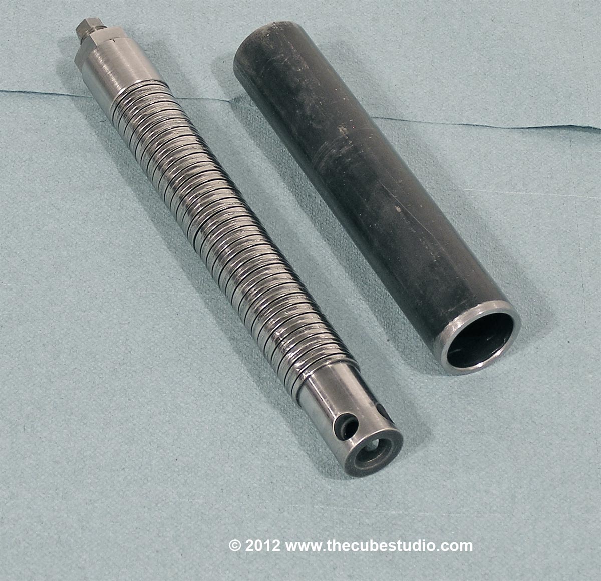
Raised ridges from the punch operation were left on the edges of the springs. These uneven raised edges, when facing each other in the stack, refused to stay aligned. The ridges would slip off each other driving the spring sideways with a very great force. The only solution was to remove this ridge and radius the ID slightly  - by hand - on each of 60 springs. Now they are behaving, but that is WAY too much time to put into that component. For anyone contemplating a build like this, I would recommend buying the springs from the manuf, or at least know the brand name of the springs. However, reality check; I found springs that were nearly $4 EACH. That makes a US$240 stack. The stack I used was a little over $40 and the coil spring was a bit over $50. Functionally, the springs are fine and in any un-stacked application, the ridge would be insignificant, but for stacking, the quality of the finish must be very good or the springs will splay out.
 
Quote
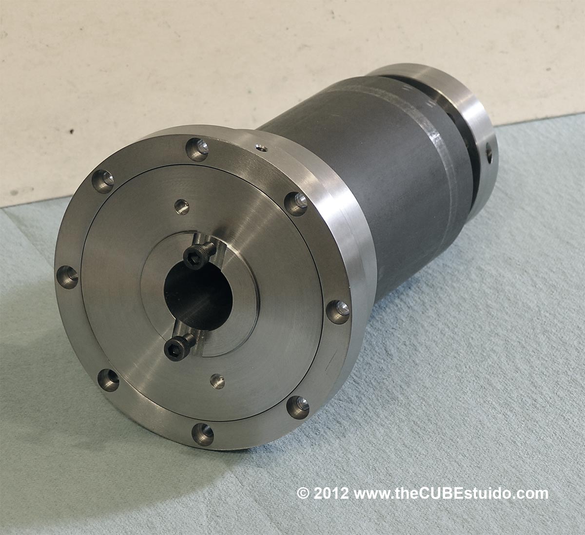
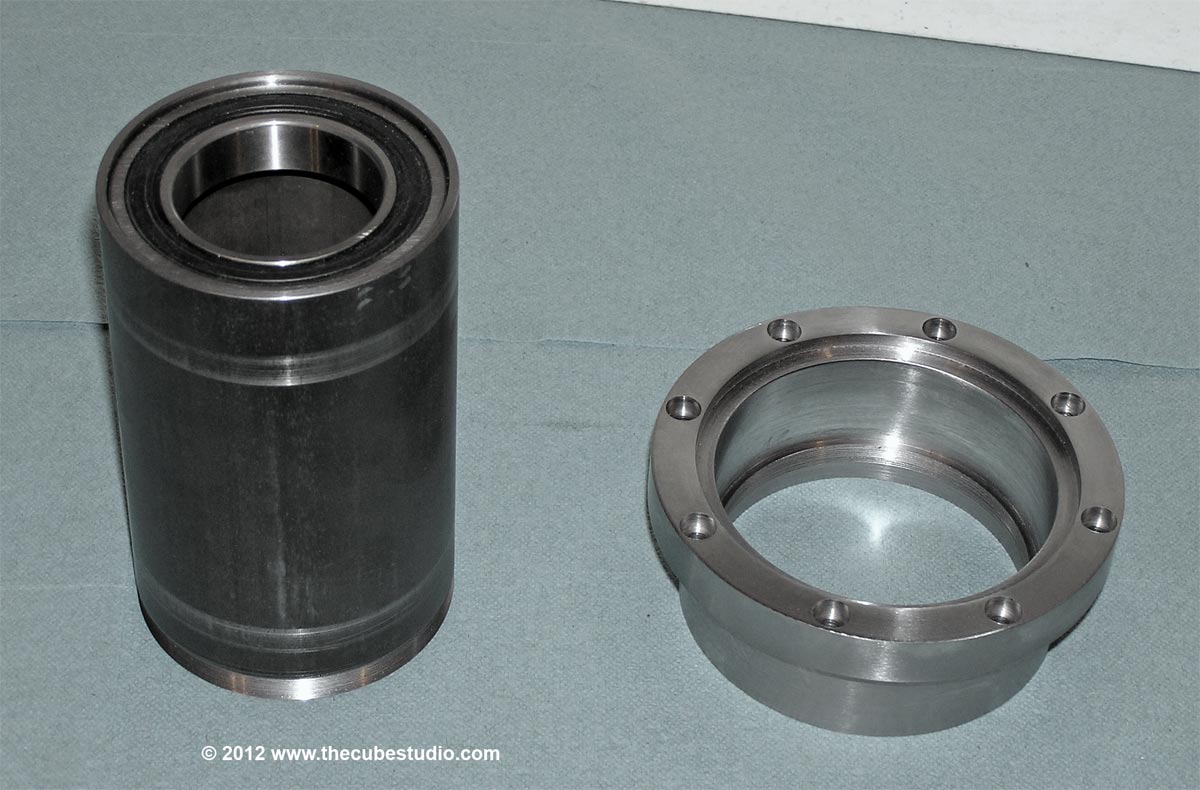
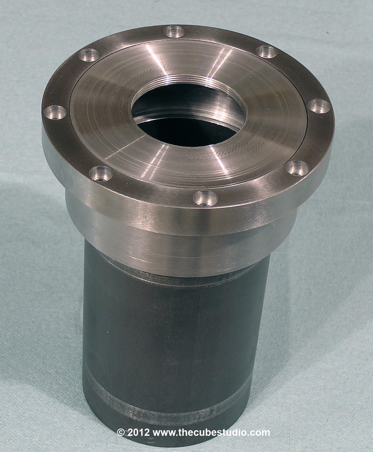
The way the cylinder and springs are designed on the Beaver mill is quite nice I think, spindle, drawbar and cylinder are all in one unit thus no pressure on bearings at all as far as I can see.
Hood

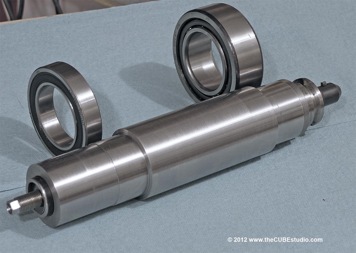
My R8 power drawbar did not put pressure on the bearings. But those are much smaller bearings. I just went thru the exercise of calculating the leadscrew force and the 400 watt motor faults at about 650lbs and the 750watt motor would push the head with about 1,250lbs. The drawbar is supposed to be run at about 600lbs, but even running it at 1,000 lbs, the release force is not much more than the spindle would see from the axis drive, albeit a lot more frequently. This is all academic really, because the bottom line is that the release is about 1,400 lbs and the bearing is rated over 10,000 lbs, so there is no concern over hurting the bearing.

The R8 drawbar was a different story with a much higher release force and a much smaller bearing. Actually, one can only imagine the actual force on a typical R8 spindle bearing that is generated by the shock force of hammering on the drawbar to release the collet.

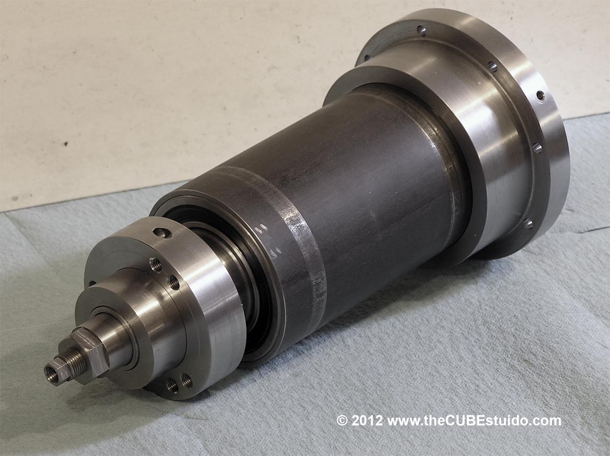
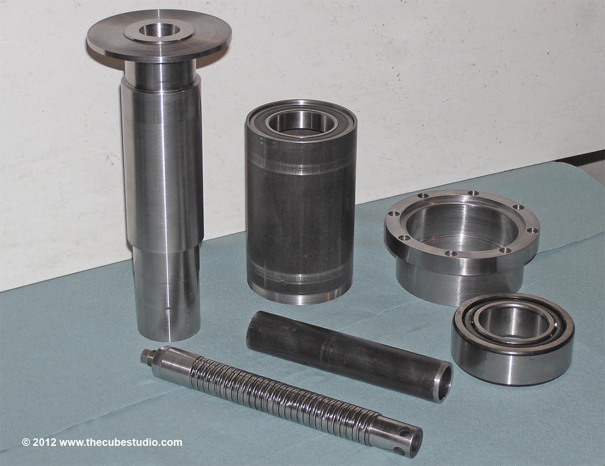
Still, There is a large steel collar on the drive end of the spindle and it would be easy enough to just fork on that to eliminate release pressure on the bearings. Perhaps I will do that. This is a first prototype so it is 'legal' for me to change my mind 50 times as I go thru the build . .  ;)

565
The lower bearing is pressfit on the spindle and in the housing. I use Loctite 609 bearing set as well if it is a steel bearing in an aluminum housing. I will use that here as a precaution. Mechanicallty there are pins that prevent the bearing from moving and lastly, I have decided to preload the upper bearing in order to take the release stress off the main bearing. So altogether I think that is 4 methods of retaining the bearing.

This wraps up the spindle project. If anyone is interested in purchasing this prototype then I will build a larger one, otherwise I will use it in the new mill as-is. PM me if interested.


Here are progress shots of the completed spindle. All that remains is the drive pulleys, which attach to the steel clamp collar shown.

Two sets of holes in the clamp collar are to mount items above and below the collar.


From the front, you can see the Labarenth seal and the mounts for the drive dogs.


566
The lower bearing is dual row angular contact and is preloaded. It is ABEC3. The spindle nose has a threaded retainer, so if I chose to use separate ABEC7 angular contact set, the retainer would clamp them together (preload is already set on these bearing sets). In either case, the upper bearing is pressed in (lightly) to the case and floats on the spindle (snug). The housing is steel, to the expansion difference will be only the delta in temp from the spindle to the case, which will be minimal.

A C3 top bearing would probably have enough clearance to not need to float, but I did not do the calculations on it because I elected to float the top bearing anyway.

The lower bearing will take the full force of the release, but it is well within the static load spec on the bearing. Again, I have not done calculations to quantify, but I would not be surprised if the force required to fault the Z axis is greater than the release pressure. 400 watt motor thru belt reduction to a relatively fine thread ball screw. The new mill will have a 750 watt Z axis motor because the head will be much heavier.

Edit: incidentally, I am of the opinion that the big CNC manuf spec a certain finish on the Belleville springs. If I could do so, I *might* be inclined to use them again . .  unless the cost was prohibitive. I will never use off-the-shelf commercially available Bellevilles again for this application. In fact, I am considering selling this prototype BT30 and making a larger spindle  . . . for which I would be able to use the coil spring.


567
Couple more progress photos:

The latest addition to my 'mini machinign center' is the horizontal spindle. Here making quick work of the bolt patterns and countersinking.


Final fix on the friggin' spring stack. I despise these things.


Housing parts:


And finally the whole gang in a 'family' photo:


Some detail items and final assembly and the spindle is complete.


568
Thanks again for the info, Hood. You and BR and Himmy and many others need to be recognized occasionally for the vast amount of time you all spend helping others.

So Kudos to all and please know that it is much appreciated.

Quick update on the spindle. Spindle proper is completed except for grinding the bearing pads and drill/tap for the drive dogs.

Progress photo here:


569
Very nice. Thanks for taking the time to explain.

So you are using digital inputs. Mitsu has both digital inputs and you can also talk to the drive, but thru RS422, so a converter is needed. I have acquired the converter, but it is still in a box . . . somewhere . .

I also have a couple of Copley drives and they are straight RS232 serial and have a text based command set. Very easy to use, but no digital input option like the Mitsu. Each has its plus and minus.

You have given me a lot of good info to think about as the ATC project grows closer. I will have the spindle done soon.

Q: if you don't mind sharing, how are you locking the turret?  It appears to be very heavy and takes a moment to settle. Do you have a damper on it?

570
. . . .  another nice feature, the drive can be set to take the shortest route between index positions and thus it can go both forward and backwards depending on the index you call, this makes it ideal for a turret or an ATC.
Hood

It does sound ideal. I was directed (by BR, I think) to a video where a fellow (founder of Fanuc or something like that) had made a very nice ATC and apparently went on to make an entire mill. He used a Geneva mechanism in his as I recall. That was the only thing I did not like about it. I will check to see if Mitsu has a similar feature to what you describe as I have a spare 400 watt Mitsu motor and drive on a shelf. The Mitsu has the real time auto tuning which is particularly good for the 4th axis, but that feature has little advantage for a tool turret and what you describe does seem like the hot setup! Especially since it is independent of MACH!

The drive you are talking about is Allan Bradley, is that correct? (in case the Mitsu does not have such a feature). How do you talk to the drive?