Hello Guest it is April 26, 2024, 01:13:04 PM

Show Posts

This section allows you to view all posts made by this member. Note that you can only see posts made in areas you currently have access to.


Messages - simpson36

551
Spindle completed. Actuator completed except for lockout solenoid which is on order.

I made up a test rig from scrap that duplicates part of the future head. The initial test was added to the previous fragment. and can be seen here. If you already say the first fragment, skip to 00:40 sec.

That wraps up the spindle and PDB. The ATC is next, but I have had some other stuff come up so it will be a while before I can resume this project.

A big THANK YOU to all who participated in this thread.   :) :-*


www.thecubestudio.com/BT30SpindleProject/BT30SpindleTestRig.wmv

552
I guess that should be enough force.  :-)

Some pretty outrageous drawbar force numbers have been batted about for the big mills. It is hard to know what the facts are because the 'specs' never come with any references, but in any case, I am not developing these machines just for benchtop mills. Everything can be used in 24/7 production shop floor. The actuator can easily push 5k with a 2:1 safety factor. There is an intentional (and easily replaceable) weak link that fails just under 10k (hence the max force spec).

553
Steve,

I guess that should be enough force.  :-)

So.....  I'm guessing you have a two-stack 4" cylinder, generating about 2500#, with a 1:2 cam arrangement pivoting on the shaft in the lower RH corner of the photo?

Close. Two stack 3", 4:1, no pivot.

Compactness was a design goal. Actually, I did three complete designs using different methodology and selected this one as the best all around.

Quote
I'm curious why the release is so slow?  Is it a single-acting cylinder, and that's just the bleed-down time?
Double acting. I added an edit to explain that this is configurable and I have it set conservatively. Essentially instant speed is available, but the cost might be high, so other than torture testing, I will want to run it as gently as is practical in actual service. I have a restrictor on the exhaust.

554
Drawbar Actuator is completed. Met and actually far exceeded all design goals.

Specs:

Travel:  .25"  (selectable)

Working Downforce @ 100psi with .25" travel: 5,281lbs  (in service, this will be adjusted down to about 1,500lbs via pressure reg)

Max Downforce: 9,127lbs

Apply time: < 1 sec            (configurable via tubing size or orifice, can be almost instantaneous, but imposes shock load)
Retract time: approx 2 sec  (configurable as above, soft retract is intentional to limit shock load)
Electric Solenoid operated positive mechanical lockout. Actuator cannot release drawbar unless solenoid is activated first to withdraw mechanical interference.

Currently presses against spindle bearings (top bearing if pre-loaded). Can be installed in a floating configuration and forked to whatever is available on the spindle for zero bearing load. This actuator generates nearly zero shock load so bearing loads would be the compressed spring force only.

Overall dimensions installed orientation:

Length 9.35"
Width 4.56"       (solenoid adds approx .65" to this dim on one side)
Height  4.49"


555
Will this thing make coffee in the morning as well(;-).

No, but there is a Margarita adapter for the ATC.  :D

Quote
Have you considered just adding the turret mechanism to the spindle housing and just index the spindle then relock the turret solid each tool change. You could add the index slots to the spindle housing then use the Power draw bar to lift the turret off the slots then use the spindle motor to rotate the turret then release the power draw bar to engage the slots again to lock it down.

When you say spindle 'housing' I think you mean the spindle itself? If so, then yes, attaching to the spindle nose may be the way to go. I really wanted to avoid having the spindle stick down past the bottom surface of the head, but that may be what I'll need to do.

Quote
That way you do not need a huge servo OR brake mechanism JUST to hold the turret in position

 
You have a knack for making suggestions right AFTER I have finished building something . .   :(  
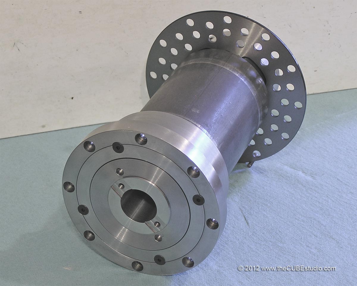
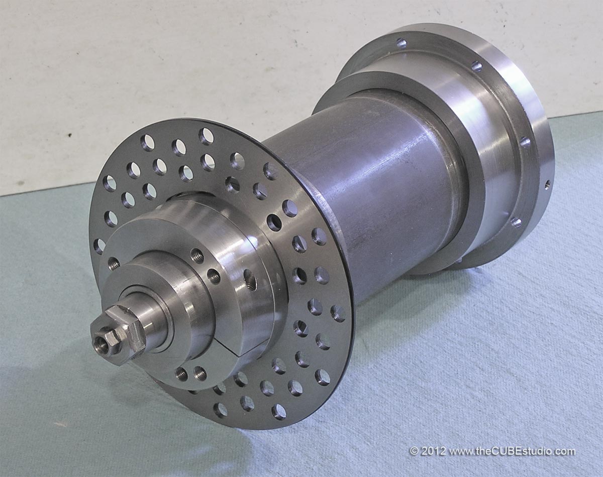
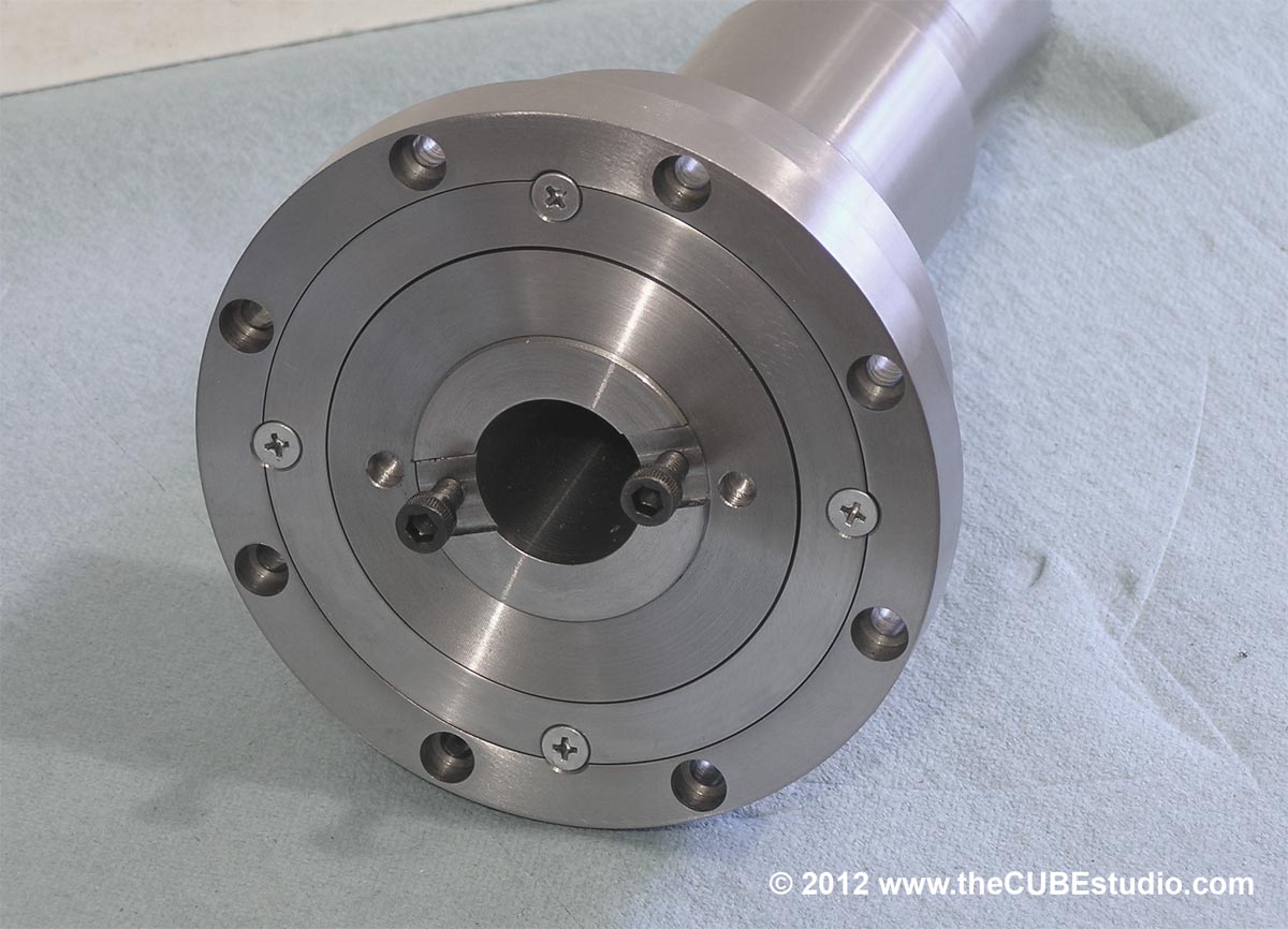
However, notching would not be adequate for the spindle because fine adjustments are needed for the tools. Something that is extremely cool is to cut up to a shoulder in one direction and then just rotate the tool and cut up to another shoulder in the opposite direction. Saves a tool change! But the rotation is not exactly 180 degrees, hence notching would be an impediment. Besides that, I have already added a substantial rotor (see photos) and will use one of the 4th axis calipers with it. You can't move the 4th axis spindle or the mill spindle when locked, trust me on this.

Quote
When NOT in lathe mode the spindle then uses a standard BT30/40 tool holder.  IF you are going to move up to 40 you might want to consider Cat40 as they are more common in the used market than BTs.

The jury is still out on this question. I'm working on other stuff right now so I will revisit this question later and consider all suggestions. I have completed the PDB design. Quite unique I will say . . extremely compact. It mounts on the head, so I will need to mock up a head to do any testing. Hood expressed that he liked that on his mill a lot of stuff follows the head around, I have that as a design goal.  We shall see.

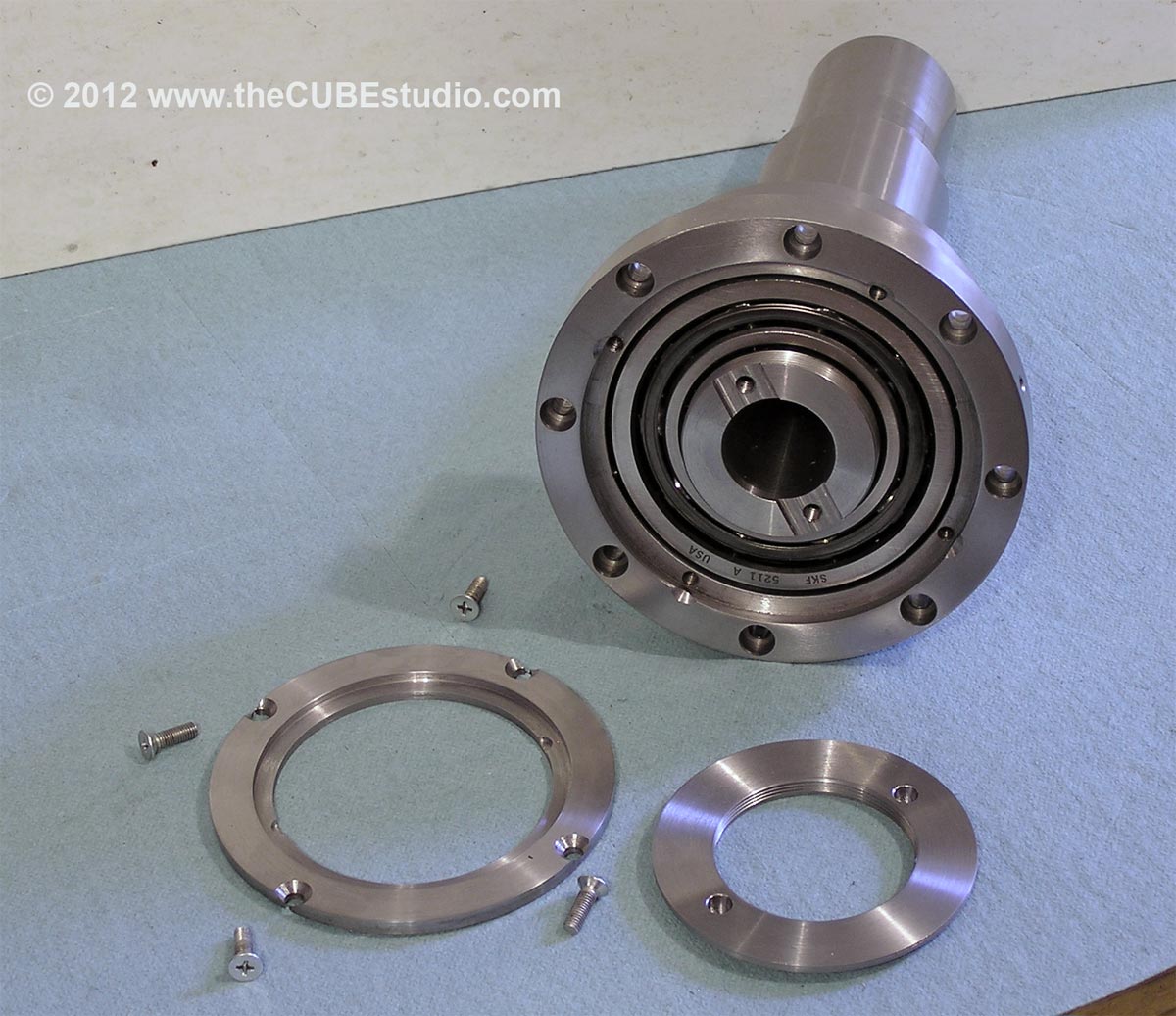
Incidentally, 'your' bearing retainer has come in handy as a leg up on incorporating an oil seal.  SKF has some contact seals good for about 7k RPM, so I am going to use that instead of the labyrinth with the current bearing because I do quite a lot of grinding. I have added a positive pressure purge to the housing already, but that can just be plugged. The labyrinth and purge is still necessary for high RPM with the precision bearings though, so it is good to have also.

Spindle lock rotor:


556
I don't just want a 40 series spindle, and I cannot use an off-the-shelf spindle. It is not that simple.  

What I want is an ATC. The spindle is just a piece of a much larger puzzle, as is the PDB. Actually, the ATC itself is part of a larger project. The concept of an ATC is not limited to swinging adapters around. A tool turret is also an ATC, in my view, and I am contemplating having both. Although in the 'mini-machining-center' configuration, the tools in the mill spindle can be single point tools for turning operations (see image below), my InTurn™ 4th axis' unique turning capability would not be fully served by a convectional milling machine ATC.  The 4th axis wants tools pointing at it. That is why I did the Horizontal Spindle project. I need the big spindle because it will hold not only single cutting tools for the 4th axis, but potentially also a tool turret. I have the static loading capability that I need, but BT30 is starting to look maybe a bit too small to hold a tool turret, There are other solutions to that problem, if indeed it becomes a problem, but most would require a new spindle design with a nose specifically capable of holding a turret, either by a larger adapter or a mount on the spindle shaft itself.

Hopefully that clears up some of the mystery.


557
HIYA Steve I don't know how you are going to compare price wise but this is about what you are building.

http://www.tormach.com/store/index.php?app=ecom&ns=prodshow&ref=30505

(;-) TP

I have been aware if the Tormac spindle for a long time. It was quickly eliminated for two reasons.

1) it is toy sized. I know it is difficult to tell from a photo, but for scale compare the BT30 taper to the housing size on my spindle and the Tormac. 
2) the Tormac has only a drawbar and no option for anything else.

Price? I don't think the Tormac spindle is equivalent to what I built. The price of the Tormac would get you the ABEC 7 bearing set for a 55mm shaft. I did a lot of bargain hunting and there is still more than the price of the Tormac just in parts and materials in my spindle. I would have built a new spindle long ago except for the $500 stud gripper. I have mentioned this before, asked about it, done extensive searching, best I eved did was I found one for about $400, and remeber this is just for the gripper fingers, nothing else.  I never found a used gripper and never found a ball type gripper new or used.

Probably I will not produce the spindle so I have not worked up a price, but it would be more than the useless Tormac toy and less than TECO or equiv precision sindles. I would sell the prototype for a reasonable offer only because I am contemplating going with a larger adapter size and it is not possible to recut the spindle for a larges adapter. Once I start using the BT30 spindle, I will be collecting more and more BT30 tooling which will make it a lot more expensive to switch to a larger size down the road. On the other hand it is always difficult to sell my prototypes and I have not listed the spindle, nor my 4th axis prototype. I know it is idiotic, but they are like my babies and I always want to keep everything.  :'(

558
Steve,

It's a thing of beauty!  A few things I'm not clear on:

Are the 4 Philips screws what retains the lower bearing?
Yes, the screws, in part, retain the bearing. The screws shown are temporary until I grab some socket flat heads in that size. You know how it goes, I have ever size above and below . . .

I say 'in part' because there is also a press fit as well as being 'glued' in with Loctite bearing retainer.

Edit: oh yes, I almost forgot: mechanically there were also already pins thru the housing below the bearing.    

However, taken alone, and using only rough numbers because we are not even close to the wall, the bearing is rated around 10k and 4 of the proper fasteners will resist about 9.5k, so even without the press fit, glue, or preload on the top bearing, the lower bearing would be toast by the time the screws popped.

Quote
What are the two "dimples" on the inner perimeter of the (assumed) bearing retainer?

What hump?

kidding . . . those are just the remnants of the spanner pin holes. What is now the 'retainer' used to be the full plate with the labyrinth seal at the edge, so it had spanner pin holes for 'wrenching'. A new smaller plate takes its place, this time with the seal between the outer and inner disks.


559
General Mach Discussion / Re: Lathe Spindle Speed Control
« on: September 06, 2012, 01:07:07 PM »
Take a look at this video and see if you might get some ideas from how I implemented CSS (I called it 'AutoSpeed Mode').

What is does is collect Z or Y axis position from MACH thru ModBus and a Brain program and uses it to calculate the RPM and generates the Step/Dir stream to the 4th axis Servo drive.

You might be able to do something similar except instead of generating the step/dir signals for the spindle motor, have a lookup table for the vari drive positions and send the appropriate commands to the vari-drive actuator (be it a stepper, servo, hydraulic cylinder, solenoid, or whatever)


http://www.youtube.com/watch?v=vBLuF_F2_qs

560
OK, two more pics and we're done. Here are the bearing retainer parts and the assembled spindle nose. All that is left are a couple of drive dogs. Anybody know if the dogs are hardened on a typical BT30 spindle?

I will need drive pulleys and a disc brake rotor for the top of the spindle, but I am note sure what arrangement I want  for those yet, so I suppose the power draw bar is up next.