491
General Mach Discussion / Re: BT30 spindle from scratch - with power drawbar and ATC of course
« on: October 08, 2012, 06:46:00 PM »
Time for new stuff. Two topics the carousel pod and the claw. NOTE the photo attaching did not work again, so I am using the previous method
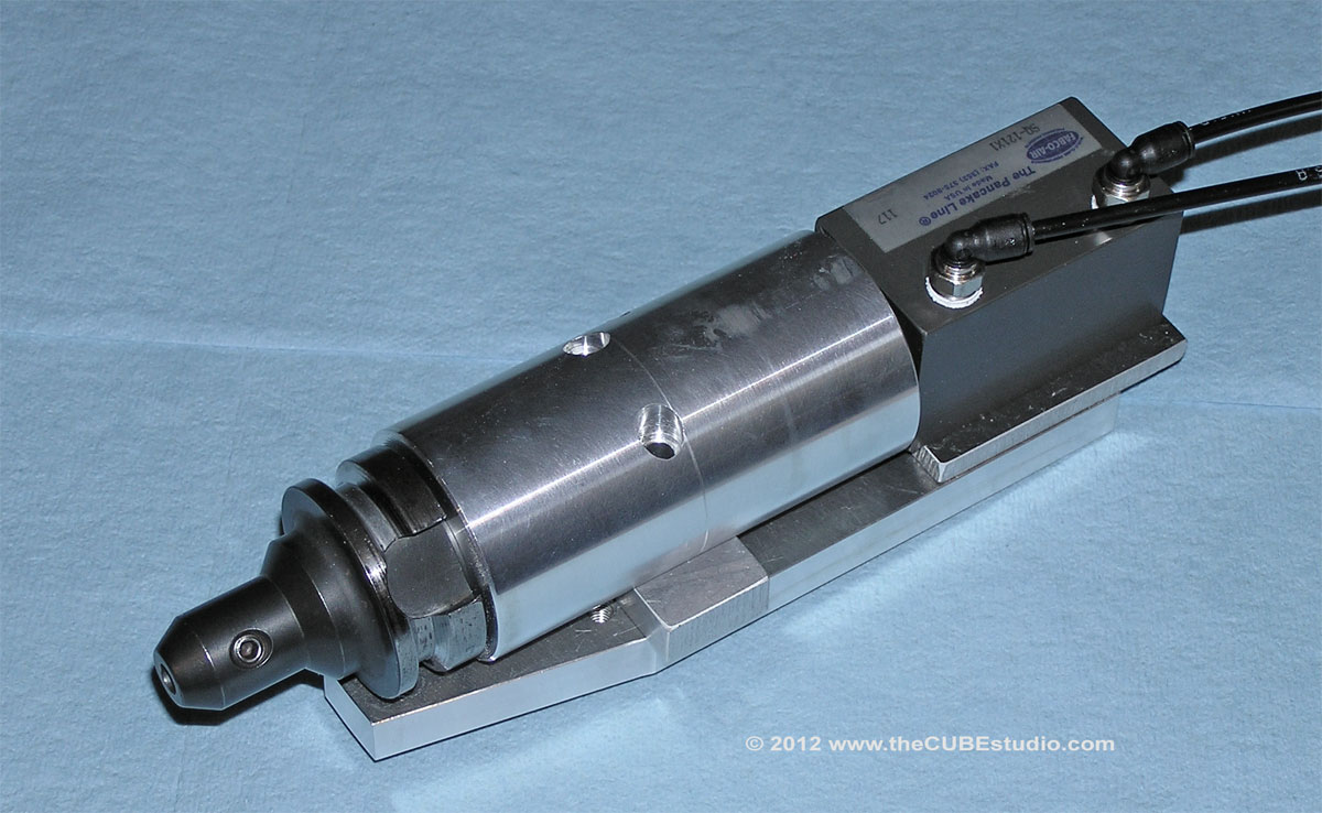
First photo is a test rig for the prototype # 2 gripper type Carousel pod. It works perfectly, holds the adapter tight against the o-ring seal and is just cool looking. So after much contemplation, Ive decided against doing the hybrid prototype and will stick with the gripper pod. It is a little bit more challenging to make and more $$, but not when compared against doing an entire third prototype. I wanted to avoid torquing the carousel with the release cylinder above the pods, but the force needed to yank the adapter out of the hybrid pod might well be more then the cylinder exerts, so that became something of a moot point.
Enough about the pod. On to the CLAW . . . dun duuuun <- scary sound effect
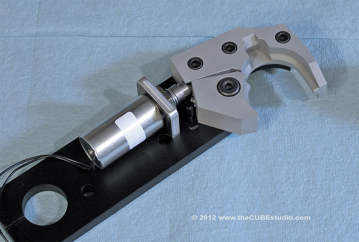
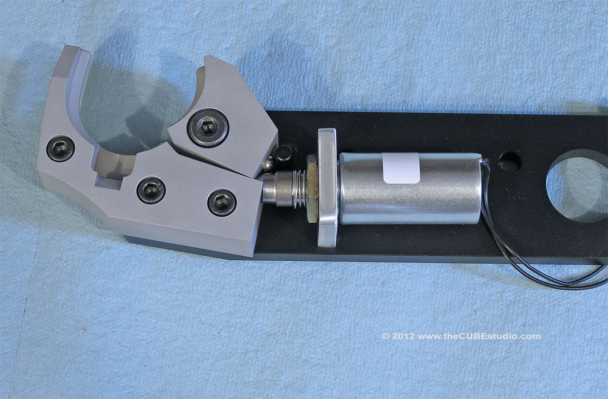
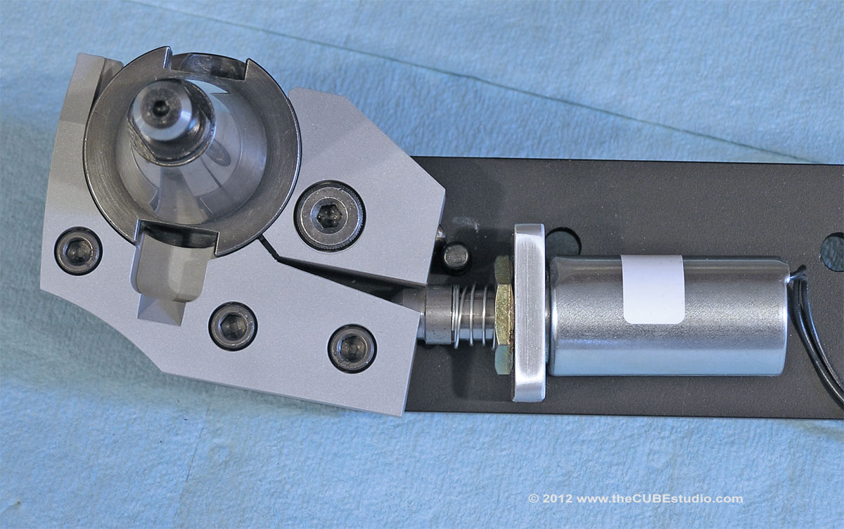
OK, the claw has a rocker in place of the finger on the previous . . hand . . (it was not strong enough to enjoy true claw status). The rocker snaps smartly to its open and closed positions by way of an over-center spring plunger arrangement. The force is quite high and it requires a very enthusiastic deceleration to dislodge the adapter.
Which brings us to the safety interlock. When the claw rocker is in the closed position, the spring loaded interlock plunger moves between the rocker and the claw body, interfering with the claw rotation and preventing the release of the adapter. The plunger is retracted by the solenoid which allows the rocker to . . rock . . and release the tool. The rocker remains in the open position under spring pressue until it is again slapped around an adapter. I have messed with it a bit and it seems to be working as intended so this will be the final design for the Claw. The pod will get some minor improvements to make the interlock a little bit more bulletproof and that wraps up the tool transfer mechanisms for the ATC.
Last order of business will be the actuators for the arm and the carousel, but that will have to wait as I have higher priorities ahead of this.
I hope everyone has enjoyed the thread so far. My objective here was not to bring cool finished parts for show and tell, but rather to show the development process that results in the cool parts . . including the fails which are part of the normal flow. You hope the design will pass all testing and be a done deal (like the first spindle gripper), or perhaps have some typical adjustments and minor changes and still move into the light. Really you don't like to abandon finished prototypes altogether, but in engineering we have a saying; 'you can't polish a turd'. Mo better go back to the drawing board than to break out the brasso and have at it. The first claw was a clear fail . . which is bad. The first pod, while functional, was supplanted by a superior idea . . which is not so bad.
First photo is a test rig for the prototype # 2 gripper type Carousel pod. It works perfectly, holds the adapter tight against the o-ring seal and is just cool looking. So after much contemplation, Ive decided against doing the hybrid prototype and will stick with the gripper pod. It is a little bit more challenging to make and more $$, but not when compared against doing an entire third prototype. I wanted to avoid torquing the carousel with the release cylinder above the pods, but the force needed to yank the adapter out of the hybrid pod might well be more then the cylinder exerts, so that became something of a moot point.
Enough about the pod. On to the CLAW . . . dun duuuun <- scary sound effect
OK, the claw has a rocker in place of the finger on the previous . . hand . . (it was not strong enough to enjoy true claw status). The rocker snaps smartly to its open and closed positions by way of an over-center spring plunger arrangement. The force is quite high and it requires a very enthusiastic deceleration to dislodge the adapter.
Which brings us to the safety interlock. When the claw rocker is in the closed position, the spring loaded interlock plunger moves between the rocker and the claw body, interfering with the claw rotation and preventing the release of the adapter. The plunger is retracted by the solenoid which allows the rocker to . . rock . . and release the tool. The rocker remains in the open position under spring pressue until it is again slapped around an adapter. I have messed with it a bit and it seems to be working as intended so this will be the final design for the Claw. The pod will get some minor improvements to make the interlock a little bit more bulletproof and that wraps up the tool transfer mechanisms for the ATC.
Last order of business will be the actuators for the arm and the carousel, but that will have to wait as I have higher priorities ahead of this.
I hope everyone has enjoyed the thread so far. My objective here was not to bring cool finished parts for show and tell, but rather to show the development process that results in the cool parts . . including the fails which are part of the normal flow. You hope the design will pass all testing and be a done deal (like the first spindle gripper), or perhaps have some typical adjustments and minor changes and still move into the light. Really you don't like to abandon finished prototypes altogether, but in engineering we have a saying; 'you can't polish a turd'. Mo better go back to the drawing board than to break out the brasso and have at it. The first claw was a clear fail . . which is bad. The first pod, while functional, was supplanted by a superior idea . . which is not so bad.
 On topic, the relationship between torque, time and horepower does not change with torque, time or horsepower, so what shall we call that relationship?
