Hello Guest it is April 25, 2024, 04:16:12 PM

Show Posts

This section allows you to view all posts made by this member. Note that you can only see posts made in areas you currently have access to.


Messages - simpson36

471
Unless you saw it in the last few days that was not my Chiron but just a vid pulled off of youtube, I just got the Chiron changer working from Mach a few days ago, still not ordered the controller yet, that will have to wait until the new year :(

The one you modelled your pots on was a Beaver VC5 that was at the same place I bought the Chiron from.
Hood

Oh my, that monster is your own personal mechanical Medusa  :o   That thing is just a freak!

I will have a lot of questions for you on the controller because that will be my next challenge after the mechanics are completed. In the mean time, I'll just ponder where Medusa keeps putting those things she's holding in her 'hands'  :P

472
Oops. my bad . . . I jumped back into this thread where I left of not realizing there was a ton more stuff that happened after that!

Ignore everything I said, RAY . . until I can catch up on the rest of the progress between October and now. Should make an interesting read, but can't do it just now. Busy busy . . .

473
Hey Steve, not sure if you saw it or not but heres the Chirons changer working :)
http://www.youtube.com/watch?v=pILjZ-JXCRQ
Hood

Yes I saw this thing before so I guess you posted it somewhere. This is the coolest example of mechanical intercourse I have seen in many moons. The tool 'pods' on my carousel are modelled after a setup you showed . . I think it was on a machine you were thinking about aquiring. Does that sound right? This does not appear to be the same machine.

474
OK sports fans, I am almost to the point of working on this ATC again.

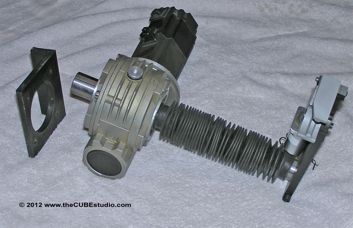
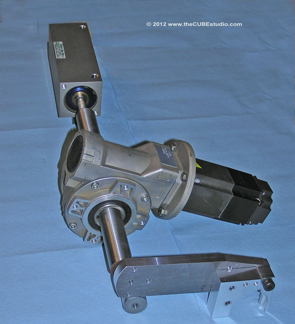
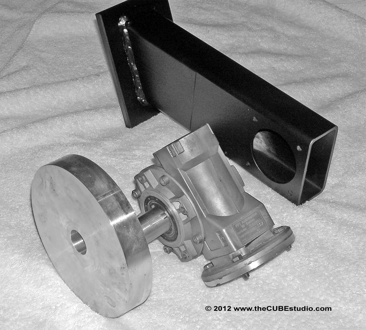
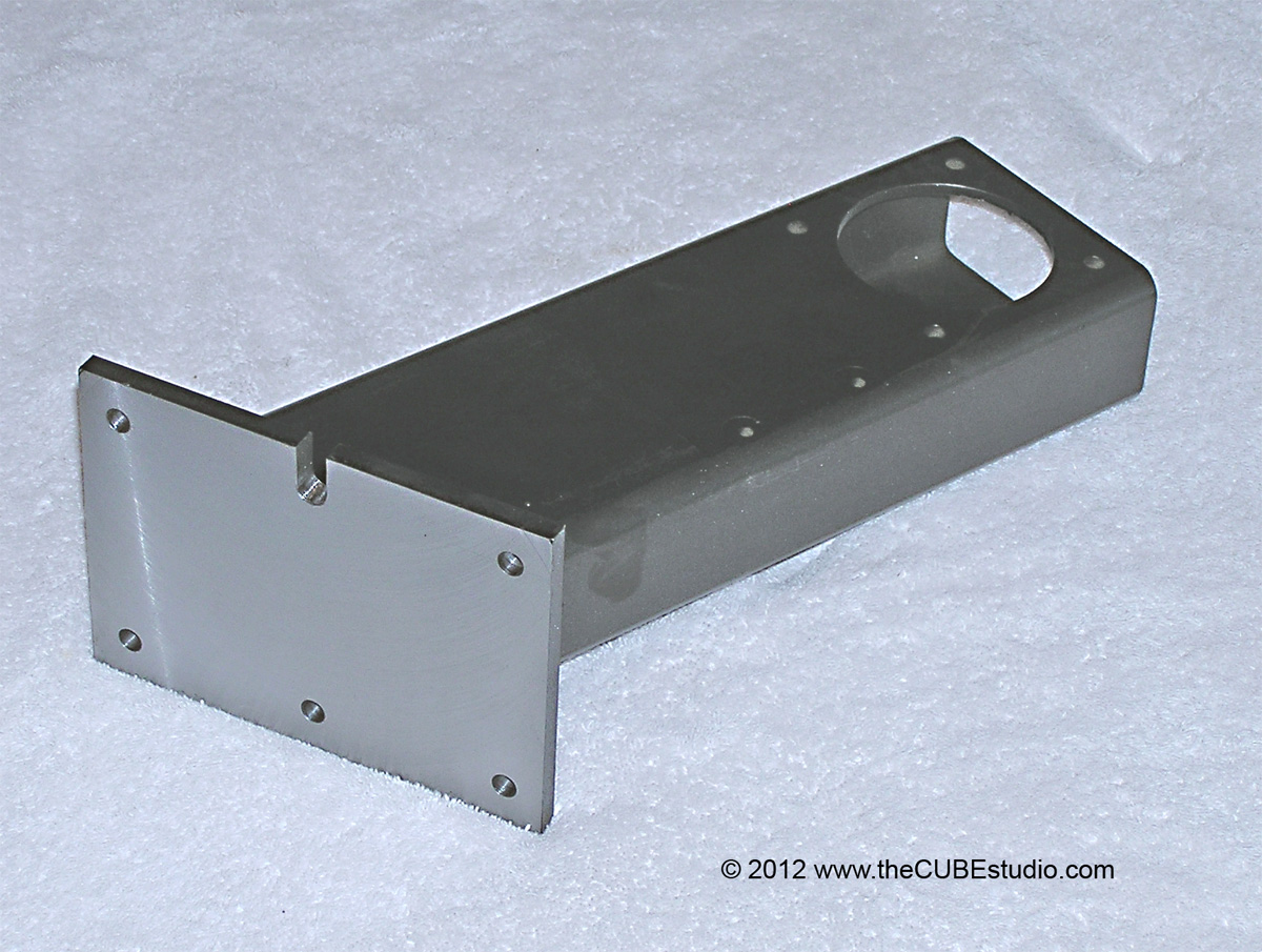
Here is the feeble sum total of my progress over the last 70 days or so . . a couple of mounts. I included an older shot (second photo) of the arm actuator to show the air cylinder that will drop the arm vertically.

I had some other weling to do to make a new ficxture, so I made up the carousel mounting arm while I had everything dragged out for welding. Then I was doing some surfacing, so I grabbed the arm off the shelf and cut the mounting pad. I was doing some boring, so I grabbed the swing arm transmission mount . .  etc etc. Little bit here little bit there.

However, sometime towards the end of next week, I will be spending about half of my time finishing this thing up. I have some material coming to partially build the new mill head so that I can mock up the final assembly and and start testing.

Oh and incidentally, I have a big fat die spring for the next drawbar and I'll be showing that coming up pretty soon. Bye Bye belleville


475

I could, of course, also go with a more complex linkage, but I really don't want to go there unless I have no choice. 

Oops! I was going to suggest you articulate as that is what I decided I would need to do when I was considering and actuator similar to what you have . . .  but  . . uh . . never mind.

Hey, is that friggin' thing done or WHAT??!!

My 60 day project is completed. I have another project that will be wrapped up in about a week and I have material on its way to finish my ATC.

Tick Tick Tick  . . do I smell Chili Beer?   :D

476
Regarding the CSMIO, yes it is more expensive but when you look at what you get it starts to look cheaper. Hood

You make excellent arguments as always, but I did not intend to imply that the product was not worth the price for a new install, only that it is not justifiable to replace what I already have which is working OK. Certainly is is an option I will look at along with Kflop and whatever else might be around when it comes time to set up my new mill. The only thing that is certain is that I am sticking with Mitsubishi drives (and motors). Everything else (including MACH) is in the crosshairs.

Incidentally, to the OP and anyone else interested, the interface board sets that I make are $50 for the set of three boards; 4 circuit input, 4 circuit output and e-stop collector or swapaxis. I can't make one set at a time or accommodate individual requests, but I am scheduled to make a batch of InTurn™ controllers in the first or second week of December to go with the the new 4th axis that are shipping soon. I can make up extra boards at that time. Send me a PM if interested.

477
I took a peek at the CSMIO and it looks like a great product. I would need the 6 axis version and an extra IO module to duplicate what I have now and the cost would be US$850 for that setup.

While I despise the USB smoothstepper that I am using, I don't think I hate it $850 worth at this point. I have not been able to spend time keeping even semi-current on the new Ethernet smoothstepper, but I recall that early reports were all favorable. If the new smoothstepper is a good part, then there would need to be some compelling reason to spend 3 or 4 times that cost for the CSMIO.

I am currently using 5 axis + spindle and might be adding another axis shortly, so the low(er) cost 4 axis CSMIO is unfortunately not an option for my application.

It looks to be an interesting option to consider for my new mill which will be built hopefully early next year.

478
Simpson have you seen the CSMIO controllers, they make interfacing Industrial hardware a breeze :) Its one of the reasons I never continued with the diff, 24vI/O bob I was going to be making for myself.

Hood

No, but I'll check it out. Thanks!  Making PCB was fun at first and I was all amazed with myself that I could make them . .  but now that I over that initial euphoria, it is just another task . . and a PIA at that.

I have the Digital Signal Synthesizer, the Swapaxis function and the Differential driver all combined on one board. This eliminated a ton or wiring and also some noise issues. I'll be keeping that board, but it would be nice to have a BOB with the 24V I/O built in. If the I/O is isolated, I would be up for trying one out, especially if they have additional I/O beyond the two PP assignments.  I think you mentioned analog inputs as well? That might be useful.

A Pokeys board is sitting on my desk, but I have only had time to fire it up and see if it would solve my I/O problem and it seems it will, but I do not have tome right now to work on the task I have in mind for it.

479
Wow, see there, you got a lot of responses already!

Mitsubishi drives (and to a degree, all industrial drives) are tricky to interface with Mach becuase they use 24V signals  . . except for the step/dir . . which are 5V differential.

You can run the step/dir single ended as shown in the manual if you follow the diagram precisely, however, since you have to drag out the soldering iron and some chips, you may as well do the coversion to differential.

What is a differential signal and why is it good?

A differential signal is one in which the signal is divided into a positive and matching negative voltage on separate lines which are twisted together in the cable. The theory is that any interference picked up will be picked up equally by both wires. Since the wires are opposite voltages, the inteference will automatically cancel at the recieving end.  This is why CAT5 and CAt6 cabling can be unshielded I am told. If I have this wrong, some of the electron guys can chime in and correct or add to what I have said.

Back to the Mitsu; what you have to be VERY careful of is that the OUTPUT side of the drive is not protected and is very easy to overload  . .  i.e. magic smoke  . .  bye bye drive.  The manual has clear diagrams on how to connect loads to the outputs, but it also assumes that the reader understands the concepts and can do the calculations needed so while there IS a diagram, there is little else in the way of instruction or guidance for the novice.

A very large problem is that there are posts in the CNCzone forum that detail exactly how to wire the Mitsu  . . incorrectly  . . and following those instructions will instantly fry your drive.

The method I took was to develop interface boards that isolate the 24V Mitsu signal from the 5V TTL BOB signals. The Mistu can be configured different ways, but I chose to have the signals be 'ON' when they are grounded back to the Mitsu. Here is one of those places where RTFM is in order if the options are interesting to you.

So, in a nutshell, I run the Mitsu OUPUT signals to an opto isolated 'switch' which then takes the BOB's own 5V signal and sends it back to the BOB. The Opto draws an infinitesimal amount of power which cannot hurt the Mitsu output and it 'switches' the BOB input on and off. A side benfit of this scheme is that teh voltage difference is taken care of and the drive is completely isolated from any 'events' which may occur in the BOB .  . for example an incorrectly installed solenoid or other coil.

On the input (top the drive) side I do the same, but in reverse. The 5V BOB signal goes to the input side of the opto and the 'switch' side of the opto in turn routs the Mitsu 24V signals to the MITSU ground . .  note do not mix or connect the signal grounds. DO ground the Mistu drive FRAME to the CNC earth ground.

The same methodology applies to the Mitsu J2S and the newer Mitsu J3. The only difference being the J2S has its own internal 24V supply whereas you ahve to supply the 24V to the J3. Here are the interface boards:


480
Like the old saying goes, I could finish that up in a couple of hours IF I had all week to work on it.

And from the same book:

Torque spec: Tighten till bolt strips, then back of 1/2 turn.

Installation instructions: Cut to fit, paint to match.

Fabrication: Cut once, then measure twice.

Troubleshooting: Machine making loud noise; turn off the machine -or- turn up the radio.

Maintenance: just another word for Duct Tape.