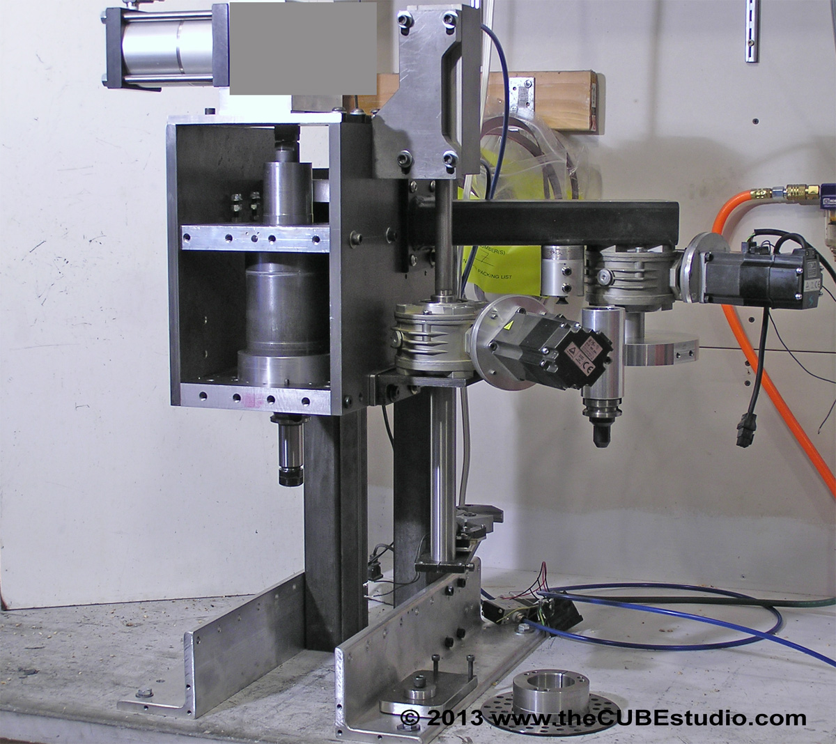
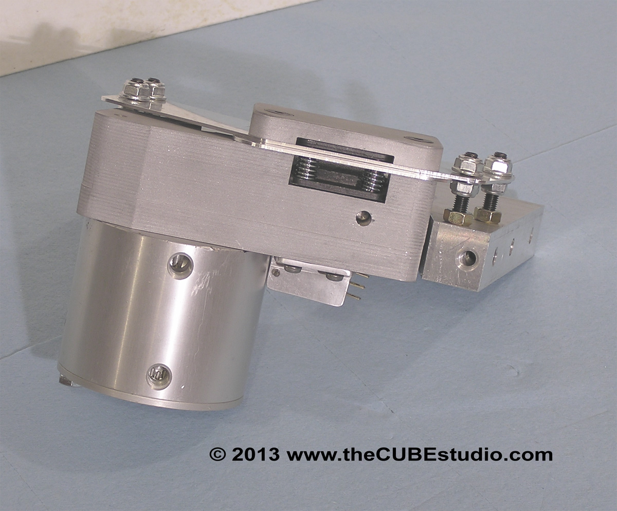
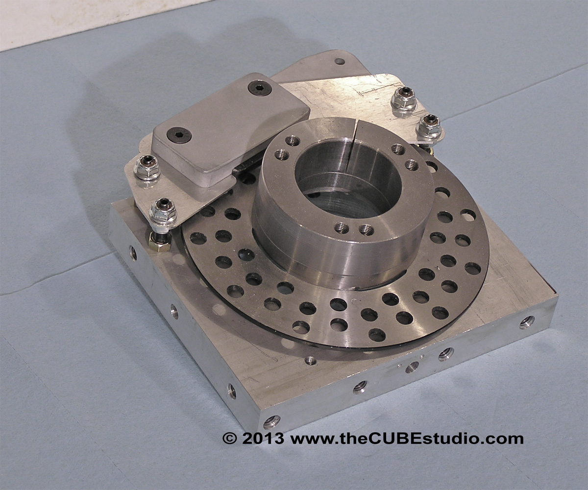
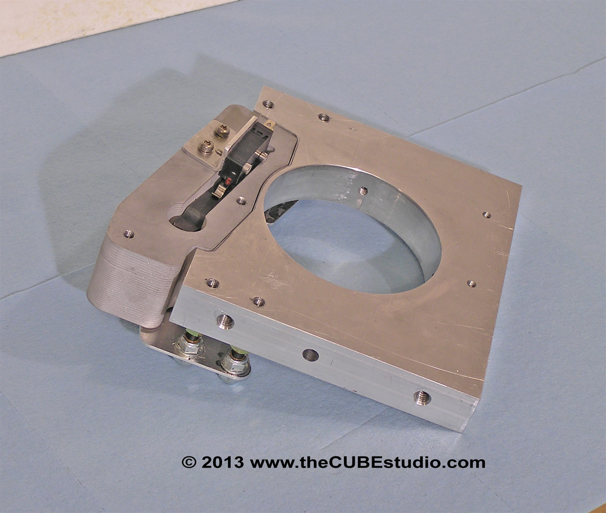
Hello Guest it is April 26, 2024, 09:15:43 PM

Show Posts

This section allows you to view all posts made by this member. Note that you can only see posts made in areas you currently have access to.


Messages - simpson36

411
To Anyone:  

- How important would it be to have a manual (pendant or equiv) method of operating the ATC? In practical terms, the carousel has to be loaded with tools and so on. My thinking is that inputting a tool change into the MDI is adequate, but it would be good to know if there are any 'wish list' methods that people would like to have, and/or to know what 'real' ATCs provide in terms of manual operation.  

- How important would it be to have the ATC perform some type of automatic tool touch off?  It would be good to get a discussion going on how this works on machines that have it, and how it might be implemented. I saw one that appeared to use lasers.


To Ray:

- You originally mentioned that you were keeping the Geneva for the carousel in your new design, but your latest description says 'servo' powered.  Are you using that term generically, as in 'motors' (i.e. steppers) or have you come over to the dark side?

- In *easily converting your new ATC to work with 30 tapers, how do you accommodate the drive dogs?

*you always say everything is 'easy'. Flying is easy for a duck. It is a bit of a challenge for a donkey. Depends on how you're equipped, I would say . . .  ;)

412

I declared by first ATC "done" some time ago, and it's been in-service for a month or more, with no problems so far.  The only "missing" piece, briefly, was spindle "stopped" sensing, which is now provided by the VFD.

OK that 'missing sensor' was the last status I knew of.  I hereby concede defeat. Just need to know where to send the beer.

Quote


My second ATC (still TTS, but could very easily accommodate 30-taper with pretty minor changes)


This will be quite a challenge, I would think.  Your TTS based design does not seem capable of gripping a stud. You must have something up your sleeve again.

Quote

If you beat me to the first "sold" unit, it won't be by very much!


Too late!  My first and second BT30 spindle prototypes are both sold and the ATC is sold, including the entire new head. Pretty much the whole setup as you see on the test stand will be installed on a new mill as part of a larger project.

Quote

 I'm actually designing this one for a machine manufacturer, and designed it specifically to be almost trivial to adapt for virtually ANY machine by changing only the mounting brackets and the length of the tool transfer arm, which can easily be made adjustable length.  Not hardly as impressive as yours, but obviously aimed at a very different market.  I actually think it's about the best work I've ever done - a number of things I've never seen done the way I did them, which is the secret to the very low cost.  It can easily sell for FAR less than any ATC of comparable capacity and performance I've ever seen.  And, it does not really sacrifice performance either - I expect complete toolchanges to be under 10 seconds, from spindle stop to spindle start, compared to 20 seconds on my current one.  The motor-driven PDB is *tiny* - only a 2" x 3.5" footprint, 9" tall, but capable of well over 30+ ft-lbs drawbar torque (actually, it's capable of generating enough torque to just twist the drawbar right off...), but MUCH faster than my current one.  The ATC is 12-tools, with a fixed carousel, only 10" in diameter, and a high-speed tool transfer arm (relatively speaking - not in the same league as yours!).  The PDB, carousel, and transfer arm are all servo-driven, and there are sensors on *everything*, so virtually any fault will be detectable.  Only one air cylinder in the whole thing, a small one at that, to operate the "lift" that inserts/removes tools to/from the spindle.  Sensors include carousel position, transfer arm position, transfer arm tool "claw" lock sensor, transfer arm "lift" position, voltage and current for all the servo motors, and more.  With luck, the prototype will be done sometime in March.  Can't start fabrication until I complete the current build (biggest to date) of one of my other products.


Speaking of 'air speed' I did some research and came up with a number of digitally controlled presure regulators, so I will be going that way instead of messing with an automotice IAC. A very clever solution though, in any case.

I do hope you plan to stick around and share this with the audience. Have you noticed the number of reads this thread has amassed? Besides,  I need you good advice as well as others. I'm not so clever really. I just listen when smart people talk. I have ordered a Kflop, so you're not getting rid of me any time soon.

Quote


When do we get video?

Regards,
Ray L.

I'm also finishing up a project, and there is another small one right behind it, so it will be a couple of weeks before I can get the rest of the ATC software done and make a video of the testing. As I mentioned, I am changing the arrangement of the air cylinder that actuates the vertical arm movement, so I will probably be covering that with photos before I do a video. Finishing the ATC is actually now a part of the upcoming large project, so while it was going to be on hold for a couple of  months, now it will get lots of attention.

413
NIce design Steve,   Might want to check your camera though it seems to have a splotch of grey paint on the lense (;-)

(;-) TP

Too funny!  Thanks for the heads up.  I'll have to get that lense checked out.  ;)

414
I am currently working on the sensors and control software. The last sensors are for the arm up/down and I could find no way to get those on the shaft that satisfied me. It is more complicated than it looks because the shaft will be covered by a rubber corrugated bellows below the gearbox and by either the same bellows or just a cover tube between the air cyl and the gearbox . .  and of course the whole shaft rotates. Also I'm not crazy about the air cyl being mounted separately from the gearbox. So I had to go on hold with that until I get a new cylinder with position sensors on the cylinder itself. I have the cylinder on the way and I plan to mount it on a tube supported by the gearbox.

My secondary task was working on the software, but I am building on top of the InTurn™ motor controller and in a moment of apparent masochism, I reasoned that this was a good time to do a major upgrade to the controller and launched into that. Among other things, I changed the interface from serial modbus to plug-in modbus . .  which took more than a few minutes.  :P  THEN, after a few brewskies, it seemed sensible to move my own development box to TCP modbus. After all the setup on MACH's side is similar to the plug-in serial, right? Well, in my setup, the "PLC" runs the modbus slave, so moving from 'serial anything' to TCP was a rewrite of a significant part of the code.

Those are my excuses. If I come up with better ones, I shall post them separately. The work is completed and working now, but apparently too late as it seems the tortoise has crossed the line.

So, Ray, if you are declaring your 'first' ATC completed including all sensors and controls, then all I can say is CONGRATULATIONS and where do I send the beer  :)

I accept your challenge to finish my first before you finish your second. However, I counter challenge you to see who is the first to have a completed and sold version operating in the field. I believe I have the drop on you there.  :-X

Anyway, at the time you took the checkered flag, I was on this lap: Note that the carousel gearbox can be rotated in 90 degree increments and the drive motor will be tucked in at final assembly. It is flying out there now to make the thing easier to work on and observe the actions.


415
OK last post for a while. I have another project hat cropped up so I'll be away from this project for about another 30 days.

Saving the best for last, here is the spindle lock for the BT30. For my current 'Franken mill', I just grabbed one of the calipers for my 4th axis and stuck it on the mill head. It works great even though it is a bit ghetto.

I had planned to use one for this project also, but alas there was no way to get it to coexist with the large diameter spindle cartridge. So back to the drawgin board for a one-off custom caliper for the BT30 project. Basically it is just a modification to the InTurn™ articulated pneumatic caliper with a longer arm to move the cylinder out away from the cartridge tube . .  which required a longer stroke cylinder, a thicker body . .  and so on down the line. It is a very cool part, I think, but I just stole if from the InTurn™, so it's not really 'new' new.

What is new if the sensor in the form of yet another little sealed limit switch that bears on the caliper arm. This will report that the caliper is either active or that is is open. The cylinder is removed in the last two photos.


416
Steve,

"The soda can is just fore scale . . I did not make that part." - I was REALLY impressed, until I read that....  :-)

Alright then, I retract me previous statement. I made the soda can . .  oh, and I invented the internet. That Gore guy just wants to steal my thunder.


Quote
On the airflow control - look at automotive idle air control valves.  I'm not sure what the airflow range is, but the functionality is exactly what you need, and they're pretty cheap.  I suspect they could be modified for lower flow, if necessary.

You DO know that IAC are steppers don't you? I do HATE steppers, you know that too right?
OK seriously that is an excellent suggestion and I have handfuls of those things around here from some Crossfire Fuel injection work I used to do. For car buffs with too much time on their hands, this may be an interesting read:
http://www.digitalcorvettes.com/forums/showthread.php?t=101038

IAC are driven directly off the ECM so it should be very doable and they are easy to mount, so I don't see much of a problem using those. Great suggestion . . .  but I still invented the internet, so there.


Quote
Those are nice little solenoids you're using.  Where do you get those?  What do they cost?  I'll probably need some on the new 12-tool fixed carousel ATC I'm designing for my new machine.  All the ones I've found so far are stupid expensive.

Regards,
Ray L.

http://www.mcmaster.com/#solenoids/=l6bf8u   scroll down to sealed

417
Another detail and then on to more cool stuff.

The seemingly obvious requirement of a counterbalance for the swing arm did not occur to me until the whole mechanism tried to jump off the bench during the initial testing.

So the counter balance is bolted on for now. The smaller round weight is for adjustment and I made up a few in different sizes from scrap. Should help considerably. I may make up an entire new arm once the prototyping is completed, of I may just weld the counterbalance to the arm . . .  or not . .   :-\


418
Steve for the column you may want to consider 6" Square X .500 wall 4130 tubing.

(;-) TP


I am considering 8" square x .5" wall or 6" x 10" rectangular x .5" wall. While it does not seem so intuitively, the tortion characteristics are the same. Either of these sizes can ship UPS in a three foot length. I really want 12" square, but the shipping is truck and just stupid expensive. A local steel yard here can get is without hitting me with the shipping, but they require that I purchase the entire 21 foot piece at something well over $1,000. They will cut it up for me though, so that's in the plus column.

Really I want cast iron. Grey cast iron has something like 30 times (from memory) the damping of steel. An important consideration. Note that only Grey iron has this characteristic, not ALL cast iron. I am thinking about using the column from one of those small el-cheapo off shore knee mills.  They are all over the place and cheap. There is one locally on Craigs list for $1,000 and I think I could get it a lot cheaper than that even.  The irony of it would be if they don't use Grey iron.  Its for sure they do not use mehanite. It might actually be better to use the steel tubing and fill it.  I just have not made up my mind on that yet. 

One thing I have decided on is the table. I have a 42" x 9" Bridgeport mill table on its way. 'Previously Owned' of course, and hopefully useable as is. Paid $500 with ship, but if I have to have it ground or otherwise tinkered with , that cost could easily double.

419
Moving on the everyone's favorite, the  <dun...duuuun>  CLAW.

Hope you are paying attention Ray, 'cause here come the sensors.

There are a bunch of things to keep tabs on with this crazy thing and some relief comes in the form of 'position reached' signals available from the servo drives. All positioning of the arm and the carousel will rely on those signal from he drives and will serve as 'sensors' for that part of the sequence.

Things that are monitored in the following photos are:

1) is the CLAW open?
2) is the CLAW closed?   (same sensor, but a different event)
3) is the interlock in place?
4) is the interlock retracted?    (same deal)

For continuity, I'll mention these as well although they will be in the next post along with the new spindle lock
5) is the spindle lock engaged?
6) is the spindle lock released?  (seems redundant, but some events need two separate sensors to monitor each state)

The first photo is the overview. The second is self explanatory and shows the switch that 'watches' the claw closure.

The last two show the switch that looks at the solenoid. This was a little more complicated in that I had to make the specialty shaped plunger from scratch and add a small rod that extends outside the solenoid case and activates the switch. These particular solenoids do not come with a spring extender so I have to add that internally to both this solenoid and the drawbar interlock solenoid.

The solenoids and the switches are sealed, but I think that I shall still put a cover over the whole works on the arm to keep junk from interfering with the workings. There are a million nooks and crannies that all need to stay relatively clean. 


420
OK, moving on to some chunky parts;

The bottom of the new head is a 1" thick chunk of pre-ground mild steel (probably A36). Initially, the new head will be bolted together and I may take it down and weld it up at a later time after all adjustment, mods, tweaks, etc are completed. The sides are also steel plate with the ATC side being 1/2" thick and the InTurn™ side being 1" thick. The entire head and ATC will be assembled on a test stand that I made up in order to work on the thing safely until the new mill column is ready. I am having a very tough time deciding what to use for the column, but that's another story.

Hanging at the top of the test stand is the head's upper mount. The lower mount is the base in the first photo. The soda can is just fore scale . . I did not make that part.  ;)