Hello Guest it is April 26, 2024, 06:16:13 PM

Show Posts

This section allows you to view all posts made by this member. Note that you can only see posts made in areas you currently have access to.


Messages - simpson36

381
Hood,

Thanks for the info and ideas. It will take some noodling to figure out how much of it might be incorprated into future iterations of my ATC.

What you are seeing here is REV 0 of the ATC and only the second prototype of the BT30 spindle. There is more to come. I have designs for a dual arm, a column mounted (and much larger) carousel, a link belt tool storage and a number of other goodies. I am also continuing to improve and expand other products. I have a new CNC rotary table (finally) and an all new tail stock design for the InTurn™ 4th axis (that I am building now) and so on,  so I'm not inclined to discount any ideas that might be useable in any component.

- Steve


382
Well, I was all excited for a while there, and I will say that the system in ingenious in side stepping the alignment issue  . .  which is a BIG issue. However, requiring all custom tool holders is not on the menu so while I can be amazed and admire the creativity in the solution, it is not an idea that I can use as it goes contrary to one of the primary deisng goals: use standard commercial/indusrial tool holders.

I looked at some of the 'pseudo' CNC toolholders such as the stuff from Tormach and some other similar stuff, but those are really aimed at the hobby community that does light duty work, can tollerate down time and prioritizes cost over performance (for the most part) and that is not my focus, so all of those type solutions got the boot.

Quite obviously, your setup is not hobby level and is well thought out and proefessionally executed, particularly is one considers the time frame in which is was built. However, while I have to admit that I would love to have one  . . because it not only performs, but the cool factor is off the charts, it is not an idea that I can run with becuase of the proprietary nature of the scheme.

Thanks for taking time to show the system and explain the operation. I found it 'fascinating' as Mr Spock would say.


383
Hood,

First, THANK YOU for the vids. Thats a piece out of your busy day and it is much appeciated.

I looked at a lot of attempts at R8 tool changers before I concluded that this was not a road I wanted to go down. Likewise, when I looked at the various tapers, I saw only fixed dogs on the spindle . .  and I looked at a lot of those spindles and changers.

The spring loaded dog seems like a brilliant solution. However . . .   it appears that each tool holder has its own bearing/brass ring brake assembly as a permanent fearture.  Is that correct?

- Steve

384
I just looked at the video fragment ans I probably should add a couple of comments:

The arm flexes up and down. This is inentional. The drawbar not only releases the grip, it also physically shoves the toolholder out of the spindle by a small amount. The arm flexes to accomodate that movement

The carousel is a bit loose. That will be tightened up during final assembly, but some play will remain intentionally to allow for minor misalignments.

The arm shaft will eventually be cut off flush with the bottom of the arm.

The arm shaft will have a corrogated rubber bellows covering it.

The arm will have a cover to keep swarf off the sensors.

The arm will move a little bit faster in the final version.

Edit: Oh and one last thing . . .  the carousel will rotate . . . so that the machine can use more than one tool  . . . :D

When I get some more pods made up, I will do another video showing an actual tool CHANGE and also the spindle homing, which is working, but not shown in the video fragment.

385
Oh BTW my Chiron uses dogs but they are sprung and the spindle is rotating at 200rpm whilst tool is offered up and thus no need for orientation.
I think the reason they did it this way is because, of the speed of the changer,  a tool can  still be rotating slightly when its withdrawn from the spindle (bearing on tool holder if you recall) and thus orientation of the holder could be out. To  keep orientation they would have had to slow the toolchange sequence down a bit and actually stop the spindle. That would make no difference to me with what I do but as the Chirons were always meant for high volume work, such as the Auto Industry, I think it mattered there.

Hood

Interesting. When you say 'spring', do you mean the dogs can move up into pockets in the spindle, or that they move out to the side (in the manner of an old flyweight governor)?

Are there ramps or something like that on the dogs to let the spinning toolholder contact then and push them to  . .  wherever they go to?

That changer of yours is just an incredible thing to watch. But tool changing at 200 RPM with drive dogs? I can imagine  . .  with some hesitation and perhaps cringing . .  yanking the toolholder at 200 RPM, but getting the toolholder IN at 200RPM just sems like all but impossible.

An impressive accomplishment to be sure. Can you describe the process in some detail? 


386
Steve,

The video is cool!  I'm almost to that point with my new ATC for all the Novakon machines  - I've had the hardware built for several weeks, but been too busy with other work to make time to do the firmware.

Regards,
Ray L.

Well, as you might agree, the software is the real challenge, especially now that I have completely lost my mind and decided to go forward with porting to the Kflop. I can tell you now that I used your name in vain more than a few times for recommending the Kflop as a 'plug and play' MACH accessory and using the word 'easy'. Note to self: When Ray uses the work 'Easy', be afraid . . be very afraid.

 The HimmyKabibble vernacular exchange rates: 
"Easy = Doable, like walking on water or spinning straw into gold."
"Difficult = requires intervention and assistance from advanced civilizations" 

Eventually, I did get things working. It is quite a powerful system, but they really need to hire you to write some manuals like you did for MACH. I will be starting on that port in a few days so if you hear your name on the wind with colorful adjectives attached  . . . that would be coming from the East, most likely . . .  ;)

387
General Mach Discussion / Re: spindle load feedback to mach3
« on: July 19, 2013, 05:02:28 AM »
There are a number of reasons to present a spindle load signal to MACH.

I tend to agree that if the only use will be a readout, then it would be a lot easier to just put an ammeter on the motor (as already described) or use the remote VDF panel (also as already described). However, there are lots of reasons that it would be useful to have the spindle load presented to MACH (by whatever means the user chooses).

However, as can be seen from Hood's posting, the uses for having torque data are only limited by the users creativity and cleverness. 

I also have plans to rout the torque output analog signal on the spindle drive to MACH for the purpose of a read out certainly, but also to monitor loads as desribed ealier.

The momentary overloads are easily accomodated with a timer as descibed in a previous post. That is not really different from the normal faulting process in the drives from follow error, overload, overheat, or a host of other maladies.  However to take it a step further, you can have MACH slow the feedrate if the load exceeds a certain amount, or at least provoide a warning that something, a dull tool perhaps, needs operator attention.  If a user has industrial drives (like Hood is referring to) you can take the load info and feed back to the drive whatever corrective action you think is appropriate.

A project on my to-do list, just be way of example, it to limit the torque output of the spindle motor for hard (rigid) tapping operations. For example, if the machine is going to tap a bunch 1/4-20 holes, knowing when a 3.5Kw motor goes over 100% is not particularly useful information . . . equivalent to an indicator light that says 'your tap has shattered'.  :'(

As part of my tapping macro, the drive will be set at some reasonable max torque for the size tap and material being cut. Monitoring this process would involve looking at values that are some fraction of 100% and could easily be less than 10%.


388
I'll talk a bit on the ATC control scheme and then post a link to a video fragment showing the arm moving a toolholder from the spindle to the carousel and back. The video is not a mock up for testing this time around. It is the actual milling machine that will be compleded and shipped very soon.
 
Earlier in this thread there was a lot of discussion on the control scheme and programming for the ATC. I started the programming using my InTurn™ 4th axis controller as a serrogate since it already was set up to read sensors, generate a step/dir pulse stream, talk to MACH over ModBuss and the processor could easily handle the tool changing sequences. Connceptually a great idea, but in reality the added ATC code was making the software very much more complicated with a net result of making the InTurn™ part of the code far more difficult to document. maintain and upgrade.  

I then made the decisiotn to move the ATC to its own processor, but that introduced a new can of worms in the form of having multiple devices communicating with MACH over mod buss. Getting one device to bi-com with MACH is challenging enough.

The solution, hopefully, is a Kflop motion controller from Dynomotion. The plan is to move the code to the Kflop for a very tightly integrated scheme which relies on the Kflop''s com with MACH thru the plug-in. This was 'supposed' to be a piece of cake since the Kflop was 'plug and play' with MACH and all I would need to do is port the existing C code for the ATC over to the Kflop and then finish it up. Well . . . .  I suppose some people would say that catching a Yetti is no problem, all you need is a big enough cage and some Purina Yetti Chow to lure the beast and badda bing . . . Yetti Stew. The reality there is also probably just a little different.

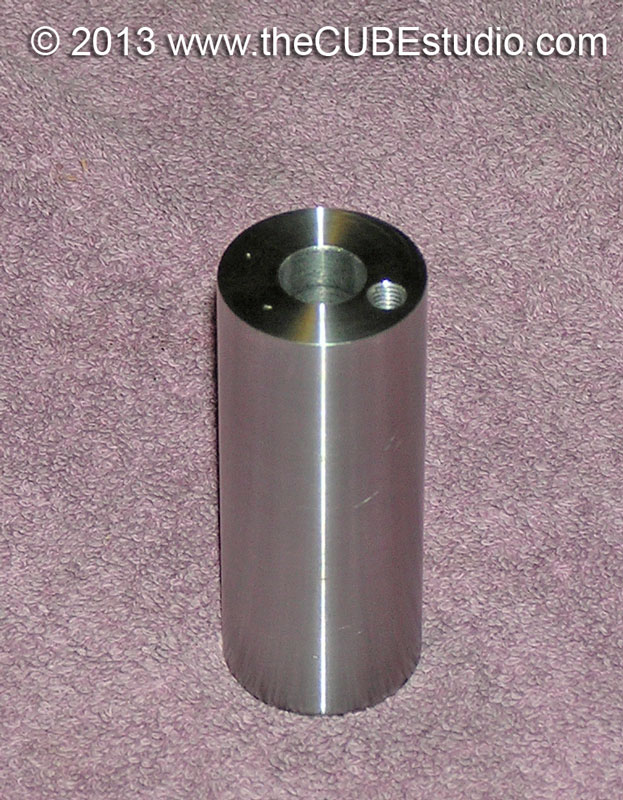
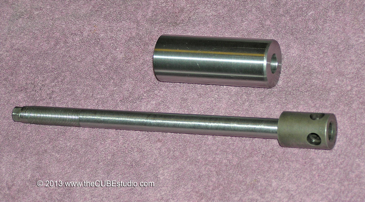
After a LOT of work, I have these guys working with MACH including the homing programs. Homing the spindle is a requisite for a  tool changer that deals with any toolholder that has drive dogs. (i.e. pretty much all industrial tapers). The drive dogs MUST be lined up, and lined up accurately, or the toolholder is going to refuse to go into the spindle. The handling mechanism ( a 'claw' in my design), has to accomodate the dogs at the spindle nose.

The last mod I had to make to the ATC was completed just yesterday and it was to add a 'tooth' to the tool storage 'pod' to keep the drive dogs aligned. During testing, the BT30 toolholders would occationally refuse to go into the spindle. It took some time to discover the cause; after delivering the toolholder to the storage pod on the carousel, the claw simply retracts to its 'park' position. As the spring loaded claw pulls off of the toolholder, it sometimes rotated the tooldoler very slightly in the pod. The next time that tool is grabbed, the dogs are out of alignment and there is no joy when it arrives at the spindle nose. A 'tooth' on the pod keeps the toolholders aligned and that problem is history.

Finally I am down to doing the final programming for the ATC on the Kflop. This mill already uses MACH's XYZABC and Spindle axis, but the Kflop has two more axis available and those are what will control the ATC's servo driven arm and carousel.

So here is a brief video showing the ATC moving a toolholder from the spindle to the carousel and back.  

www.thecubestudio.com/ATC/ATCtest-480p.mp4
 

389
After a very long stint doing a mill conversion, ironically, one of the very last tasks is completing the ATC.

The positive upward stop on the drawbar was provided by the gripper 's ball cage contacting the bottom of the Belleville spring stack. Eliminating the bellevilles left an empty tube which allowed the ball cage to move higher in the spindle IF there was no tool holder installed (the toolholder itself is typically the drawbar's upward motion stop).

So with no toolholder in the spindle, the drawbar (which rotates with the spindle)  would be pressing against the actuator plunger (which does not rotate) with quite a lot of force. If the spindle was inadvertently started at that time . . well . . not good news.

An interlock would remove the possibility of doing damage by preventing the spindle from running with no toolholder in place . . . but there no available place to put such a sensor . . except perhaps a laser looking across the spindle nose. The solution was to take the spindle apart and replace the empty Belleville tube with a solid steel sleeve that would provide the same stop that the belleville stack was providing.

Below are shots of the sleeve and it's relationship to the drawbar. The tapped hole in the top of the sleeve is for a pull stud to get the part out of the spindle if and as needed. disassembly.


And finally;


390
You are forgetting that the original intent was to come away with a retrofit kit for the IH mill. That would be difficult to accompish without using an IH mill as the prototype.

In any case, cast iron has between 6 and 10 times the vibration damping of steel, depending on the type of iron. I will be using weldments on my own mill, but my first choice would be cast iron. The welded up parts will be taken to a shop here in Dallas that will stress relieve the parts and then grind the mounting surfaces for the guides.