Hello Guest it is April 25, 2024, 08:48:26 AM

Show Posts

This section allows you to view all posts made by this member. Note that you can only see posts made in areas you currently have access to.


Messages - simpson36

1071

This thing is a lot hotter than 70C so I better do something about that.

The resistor was mounted on the outside of the aluminum box that houses the 4th axis servo drive, but it was heating up the entire box!

I have some huge old finned heat sinks from Pentium 3 CPUs. Methinks perhaps I'll bolt the resistor to one of those and mount it remotely away from the control box . .  where I won't burn the crap out of myself by accidentally touching it  :'(

 . . .  -or- . . . I could mount it to the mill itself behind the Z axis post.  That should be able to absorb a days worth of heat and would not result in having longer wire runs to the motor.

 . . .  -or- . . . I may just run without it and risk toasting the drive with deceleration voltage, although in my application, I just don't see that happening since Mach controls the decel rate.

Decisions, decisions . . . .

1072
Hood,

My bad. I hadn't even considered an AC servo. The OP is talking 4" x 12" lathe. You could probably fit that whole thing on your cross slide  :D

Do they make tiny AC servos?  If so . .  I may feel the need to tinker . . . .   

1073
You should check out the thread "Success, mini machining center . . . " in this forum. I just finished building what amounts to a lathe head using a 5C spindle and it is servo driven. You might get some ideas there.

A servo motor is basically a precision purpose build DC motor (read expensive). There is no point to using one on a spindle unless you are going to use gears or timing belt drive. The typical flat or V-belt arrangement (which you will probably use at the RPM you are talking about) erases any advantage the servo has.

You will have to rig the encoder and also an index, I would think. Unless you can find an encoder with an index rated to 15k. Here again, really no purpose to the encoder if you don't use a servo, which there's no purpose in if you use a v-belt. Catch-22

15k RPM is a dangerous neighborhood to be playing in. When things go wrong at that speed, a lot of major damage gets done in an instant. You might consider a smaller collet size for that kind of speed. 

There are occasionally precision lathe heads for 3C  (I think) on ebay that sell for about $350, so you might consider that option.

1074
Imagine the weight of the armature of an electric motor with a 45mm shaft . That's what the bearings are made for . .  my little X2 is not even going to get their attention . . . ;D

I have the Rutex driving the assembled 4th axis now up to 350,000 steps per second with awesome silent holding power, and decent accel. I can set the accel up higher in Mach by being mindful to ramp up the speed from a dead stop to max RPM if the code calls for same, but that's a compromise I can live with for now.

Still running only 62V 5A on the bench.  Will get 72V  20A when on the mill. Once i get it there, I'll be able to see my max speed and cut some metal with it . . should be fun.


QUESTION (for anyone):

I have a  1 ohm 100W power resistor in series with the motor per Rutex spec.  It is in a finned aluminum housing and it gets friggin HOT!  I have no accurate way to measure how hot this thing gets, but you definitely cannot touch it. How hot do these things run normally?


1075
The purpose of the threaded collar is to preload the bearings. The spindle runs silky smooth with zero play. The bearings are so big, they will literally last indefinately in this application.

I don't understand the purpose of a sleeve, unless you are suggesting a 'crush' sleeve as used for example in older independent rear suspensions (Corvette, etc). Those are to maintain a specific clearance as opposed to preload.

The reason I chose an open frame instead of a solid block is the difference in expansion between the steel spindle and the aluminum head. I rely on the 'spring' of the open frame to accommodate the differential without binding the bearings. I considered a steel or cast iron solid block, but I decided against that because of the extra mass it would add that has to be moved around by the little steppers on the table. Ideal would be a hollow cast iron box similar to the x2 head, but I have no way to make such an item. I did consider using an X2 head casting. The open frame also provides more mounting options. With slotted mounting holes, I can mount the 4th axis anywhere from 0 to 45 degrees on the table. although there are keyways for quick alignment with the x axis.

I've had the motor up to 3,500 RPM so far at 62V. In service, it will run at 72V, but with a 1 ohm braking resistor, so I'm not sure yet what the top speed will be. Without the resistor, it calculates to almost 4,600RPM at 72V. I'm looking for 4,000.


1076
What is the symptom you are getting? Presumably the Gecko drives are faulting?

Putting the Gecko's near the motors probably will not help. I'm a little surpsised anything is working with the gain all the way up.

In addition to what HimyKabibble asked for you need to also supply:

How long is the wire from the power supply to the Gecko?

How many amps is the power supply?

What is the resolution of your encoders and what is the speed and acceleration in Mach set to?

1077
Update: 4th axis completed. This will run at a max of 1,300 RPM or 2,000 RPM depending upon which motor pulley is used. Should be able to run all day long at top speed. There is a steel part that I make from 3/4" 12L14 steel at 1,800 RPM. it has 1/4-28 internal threads and flats on each side. This final iteration of the 4th axis will be expected to turn, drill, tap and cut the flats using one continuous program. We shall see . . . . 

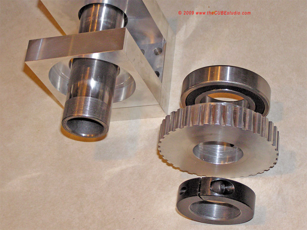
Basic drive parts moved over from previous prototype:


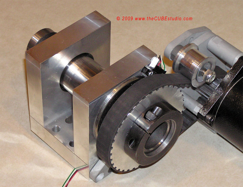
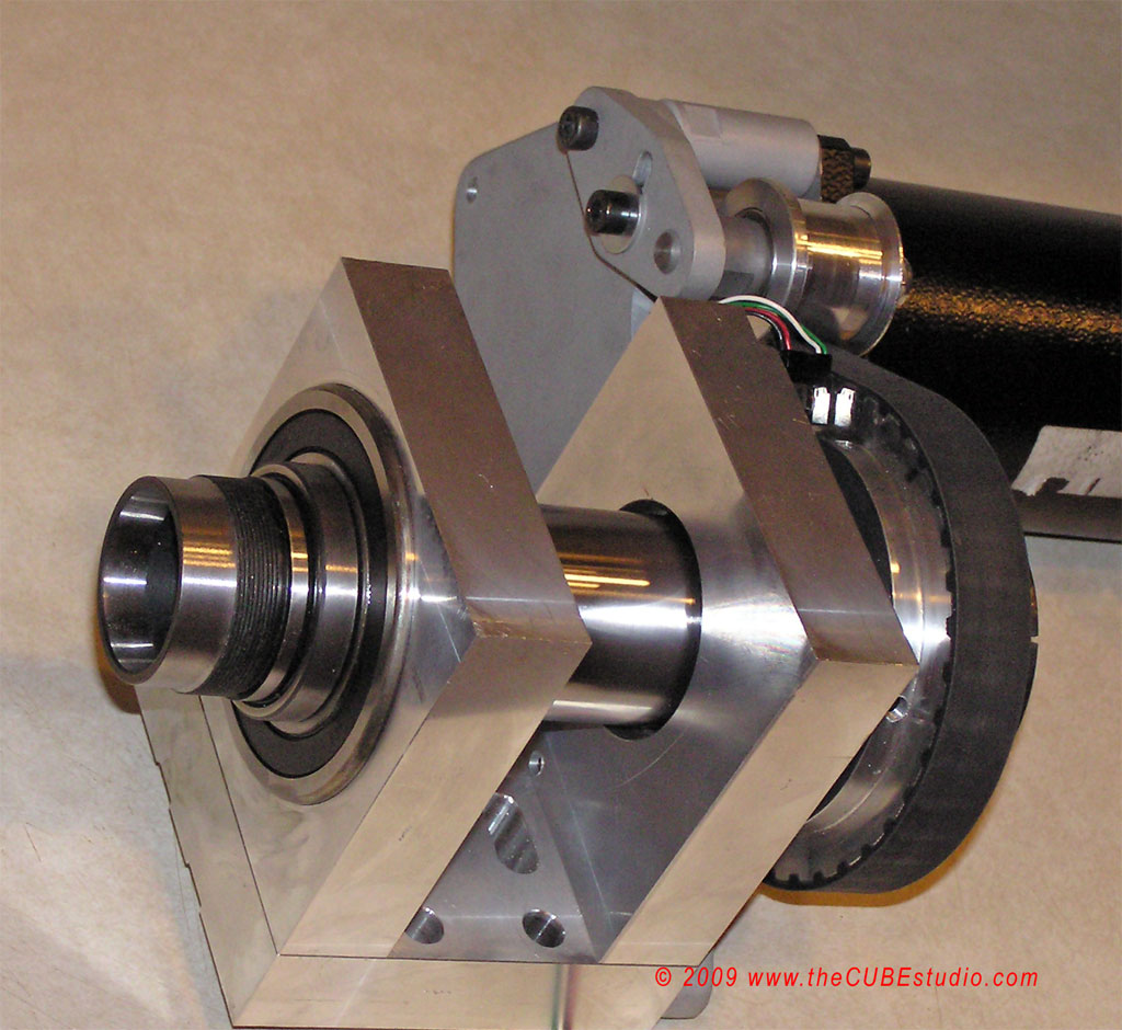
Final assembly:


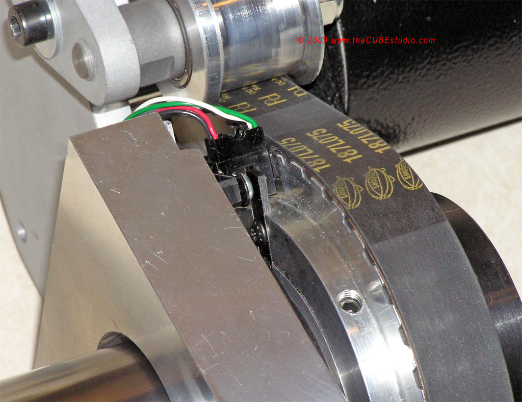
Homing sensor moved to back and oriented down to keep out as much swarf as possible.


I have my new Rutex servo drive and so far it is doing everything it claims to do, so I should get full speed and power from the motor. When I get it all back on the mill, I will make one final video and post the link. Questions, comments , criticisms or suggestions welcome.


1078
General Mach Discussion / Re: Anybody using Rutex servo drives?
« on: July 06, 2009, 03:18:19 AM »
Update: Reviews and/or opinions on the latest Rutex drives is almost nonexistent on the web, so I'm posting my initial experiences here. After I have the drive in service, I will write a more comprehensive review and comparison of the 3 drives I have tried so far, and post that on my web site. For now:  

So far, so good with the Rutex 2010. I was able to get the drive ordered with minimal hassle. You cannot do a complete order from the web site, but rather you enter an order and they respond via e-mail (promptly in my case). They provided a paypal invoice which was convenient for me and after payment the items were shipped promptly out of Missouri and arrived in a few days. Rutex does not send shipping notices or tracking numbers, but will provide the tracking number if you ask for it.

Pros thus far: The product is high quality. The anodized aluminum heat sink is thin, but otherwise the product looks sturdy and well made. The documentation is complete and accurate and following the wiring diagrams and instructions netted a working setup in minutes. The included Windows software makes tuning a piece of cake, including oscilloscope like graphs of the motor behavior. Very slick. The drive is extremely responsive to all of the settings and getting the servo motor running acceptably was a matter of a couple of clicks in the software GUI. I have not figured out the "I" part of PID yet, so there is more tinkering ahead.

Cons thus far: Before you can do anything else, you have to locate and purchase special connectors and fabricate a cable. The one oddball connector is about 49 cents and should be included so as not to become an initial aggravation and stumbling block to getting the drive going. My choices were to order from Mouser and pay $5 in shipping or drive 45 minutes round trip to Frys electronics.
An adapter plug for the power and motor connections is included. This adapter plugs into the socket on the drive and has screw terminals for connecting the wires.

The encoder wired up exactly as shown in the diagrams and worked first time. The drive will not accept a direct connection of a single ended encoder, but Rutex sells an interface for $17 that converts a single ended encoder into differential. The interface goes on the encoder and has convenient screw terminals. From there, a standard RJ45 network cable connects between the interface and the drive. Again, very slick setup. The software interface make it very easy to see in real time what the encoder is sending so you know immediately if you have a working setup.

More later . . .

1079
Quote
http://www.usdigital.com/assets/general/90_e6_datasheet_0.pdf

These are all  '5V encoder' but that refers to the supply, not the output. Mine is the 1800 line with index. I can't use the encoder index due to reduction, but just to dink around with it, I hooked it up to the BOB . . . zip, NADA. I did not pursue interfacing it, although that would probably be simple. Changing the pulse width is outside my knowledge.

The sheet state TTL output which would imply 5v?  On an open collector encoder with 5v supply you would not measure 5v without a pull up resistor, but they seem to indicate TTL for both Single ended and Differential?
I believe the 1024 pulses comes from eight bit binary value (255+1)x4, I only ever used it directly as I could always use a scaling value on the systems I used it on.
Heidenhain seemed to favour this resolution.
Nosmo.

I thought TTL simply was an acronym for Transistor-to-Transistor Logic. Older parallel ports for example are 5V and newer ones are 3.3V, but both are TTL, is that not correct?

The data sheet on the encoder says the output is 2V and there is no reaction at all from the BOB. That's about all I can say about it.

1080
General Mach Discussion / Re: CNC screw cutting lathe advice
« on: July 01, 2009, 01:18:34 AM »
BWprice100, I have to disagree with your comment about threading dies as that has not been my experince, but perhaps it is different in the UK.

I'll second everything Rich said and add that I think that considering your particular needs and time frame, that it would be a mistake to attempt a retrofit.

As a person who has started, built up and sold several businesses, and owned a small specialty machine shop, I can tell you what I would do in your sitaution. I woud consider these two options:

1) purchase a wokring used CNC lathe from a shop, dealer or hobbiest that can demonstrate thread cutting of YOUR threads on YOUR material. If they won't do that, then assume that they can't.

2) lease a new CNC machine. Tax incentives and depreciation on new equipment (at least this used to be the case here in the US) is far greater on new equipment than used, so the governement helps you buy the thing. Make the lease payments out of the profits the machine generates and save your cash.

Enjoyable conversation . . good luck with your project!