Hello Guest it is April 25, 2024, 03:20:00 PM

Show Posts

This section allows you to view all posts made by this member. Note that you can only see posts made in areas you currently have access to.


Messages - mc

Pages: « 1 2 3 4 5 6 7 8 9 10 11 12 13 14 15 16 17 18 19 20 21 22 23 24 25 26 27 28 29 30 31 32 33 34 35 36 37 38 39 »
341
Show"N"Tell ( Your Machines) / Re: Conect 121 lathe retro
« on: October 24, 2012, 02:43:05 AM »
Here's a little thought provoking issue for you.
With the (pretty heavy) X-axis motor mounted on the rear, will there be noticeable movement/vibration issues when using a front mounted cutting tool?

I'm probably over thinking it (I'm stuck in a **** hotel and never slept much last night!), but with such a large motor on the rear, it's going to cause the whole carriage/cross slide assembly to tilt towards the rear due to any play/flex. When you then take a large enough cut with a front mounted tool, it's going to counteract the weight of the motor, and the assembly will tilt to the front.
The only reason I've been thining about it, is I want to upgrade the x-axis motor, which involves a heavier motor, and moving it further rearwards to allow room for a bearing block and a proper bearing block.

342
Ahh, OK thanks.  I figured I'd have to play around with it to get it to work.  Hopefully the sensor electronics don't do anything weird on power up but come to think about I could leave it powered up and just switch the signal?
It's not very clear from the ebay listing as to how the signal functions in regard to the sensor being blocked/clear, but your suggestion is doable.

If you arrange things so once the switch closes it connects the sensor signal to the BOB then it will work. You'd just to need to make sure the BOB input is set to pull-up/down to match whatever the blocked (or unblocked if using an index tap instead of an index cut-out) state of the sensor is.
For example, if using an index cut-out and the blocked sensor signal is 5V, then set the BOB to pull-up.
That way with the index switch untriggered/open circuit, the BOB input sees 5V. Then when the switch is triggered, the BOB input still sees 5V, until the sensor becomes unblocked and switchess the BOB input to ground.

343
It would depend on how the sensor acts when the ground is disconnected and reconnected. Provided the output goes to high impedence or shorts to +5V when disconnected, and it doesn't do anything daft to the output when powered up (i.e. it remains at 5V, and doesn't spike to gnd), then it should work.

One thing I'd suggest is make the slot in the disc pretty big, otherwise there's a chance you could overshoot the slot if you're homing at a reasonable speed.

344
Orbital sander is your friend. Means you can't use wet and dry, but makes light work of large flat panels.
I'm of the opinion that working machines don't need to be works of art. They're going to get bashed/covered in ****, so I personally don't see the point in concours finishes in production enviroments. I can understand why somebody like JH does it, as it showcases the kind of work he does, and gives potential customers a good impression.

I'd personally keep it a light colour, as it'll help brighten up the workshop by bouncing light around. Nothing worse than a big dark box that just absorbs light, especially in small spaces.

345
Degrease, sand with 400(ish) wet and dry, couple coats of filler primer, flatten with 600(ish) wet and dry, top coat, job done.

By the time you've run a couple jobs, any imperfections will be covered in oil/grease/coolant/swarf.

346
Just looked at the manual for the C11, and it has jumpers to select pull up, or pull down resistor for each input.

Without going into too much detail, the NPN/PNP refers to the type of transistor used to switch the sensor output. A NPN transistor will switch to earth, where as a PNP transistor will switch to supply voltage.
In this application, using an NPN, the input pin must be pulled high, and will then be driven low when the sensor is activated. A PNP requires the input pulled low, and will then drive it high when activated.

The benefit of the C3, is it provides a TTL output, which doesn't require the use of any external pull-up resistors. The TTL actually drives the output high or low, instead of leaving it to 'float' when not activated. This is what the original C3 would do if set to Open Collector mode.

347
Thanks mc, what kind of electronic wizardry goes between the sensor and your B.O.B.?
Nothing!
It's connected through a BOB that has pull down resistors, so all I needed was a PNP version (you'd need a NPN version if you have a pull-up resistor).
All it needs is a 5V and GND from the BOB, and the output wire (I think I used dark on) is connected to the input pin on the BOB.

They come in various mounts, so you can usually find one that fits with minimal extra mount/bracket work, so check the datasheet and find one that suits your chosen position best.

348
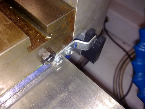
Here's what I used for the X-axis homing on my lathe -

Home Switch by mc_mtb, on Flickr

It's a Sunx PMR44P (RS part no. 480-5231).
I should really build some form of cover for it, but it's not attracted any swarf yet, and it's easily noticeable if it has. Repeatability is excellent, and only part size issues I get is when tips need replaced, or it loses steps due to trying stupid things.

349
Bad news about the transport mishap, but at least we can now make jokes about your balls getting lost  ;D

I take it you've managed to get rid of the bridgeport?


I'm hoping to arrange collection of my new toy this week, but still need to sort a few issues out so it can go straight into workshop once I get it here.

350
I found a pdf copy of the installation/user manual for the Dana/Summit tool changer on the Matchmaker, and all the wiring/programming examples are for a Bandit control. Plus it's all designed to pretty much bolt straight onto Shizuoka mills, right down to the LH spindle thread.

Pages: « 1 2 3 4 5 6 7 8 9 10 11 12 13 14 15 16 17 18 19 20 21 22 23 24 25 26 27 28 29 30 31 32 33 34 35 36 37 38 39 »