Hello Guest it is April 25, 2024, 06:09:45 PM

Show Posts

This section allows you to view all posts made by this member. Note that you can only see posts made in areas you currently have access to.


Messages - halftonner

Pages: 1
1
so is there a recommended feed per tooth for carbide bits and likewise for HSS tools?
I know that the lathe tool has in effect only 1 cutting tooth

2
Overloaded - I am agreeing with you ... but I've ended up getting myself confused .... :(

G96 = CSS
G97 = Constant RPM

sorted:  :)

Hood - one last question for your spreadsheet calculator: is the feed per tooth the cutting depth on that pass?
If not, where would I find the data to enter into that cell?

3
Head to:

http://www.hsmworks.com/docs/cncbook/en/#Ch08_CuttingSpeedsAndFeeds

and look at table 8.9

This is where i got the suggestion that G96 gives constant surface speed

Sorry if I'm sounding idiotic, but I've read and re-read about CSS, and it makes sense on paper, but in reality it doesn't quite behave ...

Hood, you mention that CSS is in units per minute, so if I have set the code to run in mm then should I multiply out the Surface Metres / Min given in cutting tables to become Surface mm / min for the G-Code?

4
shame about the CSS idea... the website I read it from was mis-informing me then :(

5
question about constant surface speed... I've just read elsewhere that G96 relates to a constant RPM....

eg
X10
G96 S1000

would give a spindle speed of 1000rpm at the current X tool position 10mm diameter .. then as the tool comes in closer the RPM increases to max... if the tool moves further away from X10 (ie X15) the spindle will slow down below 1000rpm

have I interpreted this correctly or is the S followed by a surface metres / min

Btw, HOOD, thanks for the calculator xls sheet - it will come in handy :)

6
ok, I'll have to study the inverter manual again...

and reading between the lines about css and feed rate per rev are best avoided in mach3 - I'm not too worried as I can manually program them to keep chip load and spindle speed approx constant (just need to keep a calculator to hand) :)

BTW happy new year to all, and thank you again for all the help :)

7
right, tried the inverter frequency, and it threw a hissy fit and had an error displayed (I did look it up and it was to do with current ratings. ... if it helps for this part of the question,the motor drive inverter is a Siemens G110

done the native units, and that works fine now for the feed label.

so, still no joy on getting the spindle rpm up to 2000 as claimed (partially as the motor is rated at 1400rpm and the inverter drive doesn't want to output more than 50hz atm) and still no joy on the css (g96) code yet - it still seems to misbehave, as at g96 s1 the motor runs at full tilt and warning comes up too fast for pulley. if I do g96 s0.9 it complains it's too slow for the pulley and won't revolve at all.

sorry for the loads of questions, bit I've struggled for the last few days on this, and decided it's time to ask for help :)

8
with regards to the units issue mentioned... if I set the feed rate to be 10 units / min, the slides move at 10mm / min (I've checked and measured. Also when typing in the code either via a loaded program or via the raw command line on mach3 the slides travel that given distance in mm... so apart from wanting to change the 'label' on the screen to be feed rate mm/min all seems fine - unless something had been set up wrongly by the company that used it (though I've seen the code and the parts produced and they are all done in mm and match the specifications)

with regards to the inverter frequency - the motor has a rating of 50Hz - so surely the investor needs setting to that too? OR is it the 1400rpm comes from when running the motor on 50Hz, thus if I feed the motor 100Hz it would then rotate at 2800rpm (thus giving an approx spindle max of 2000rpm). did the original Orac motor inverter drive feed 100Hz to the motor?

9
General Mach Discussion / Mach 3 & Denford Orac spindle speed headache!!
« on: December 31, 2014, 07:31:39 PM »
Hi all,

 recently obtained a Denford Orac lathe and PC running Mach 3 ... It came from a firm that produced items in aluminium and so spindle speed wasn't an issue (nor was the ability to reverse the spindle) - and so I've completed the task (as all the break out boards and motor control was in situe, just needed the additional wiring to make it operational)

The problem I've run into is trying to do constant surface speed - mathematically it is always incorrect if my understanding of G-coding is correct.

G96 = constant surface speed in units per minute ... Mach 3 is running in mm as specified in the G-Code 'header', so my understanding is that G96 S20 should give a surface speed of 20m per minute however, when working out Speed (from Mach 3 DRO) in rpm x diameter x pi = something nowhere near the supposed surface speed!!!

The Orac instructions claim that the spindle can rotate upto 2000rpm, but this turns out to be an impossibility (unless I'm missing something very obvious) as the motor is rated at 1400 rpm, and the belt drive gives a step down speed of approx 0.6, so the max spindle speed can only ever be 840 rpm!! - Though the pulley ratio is irrelevant to one extent as the speed / timing / index sensors are on the spindle, so should always give the true spindle rpm?

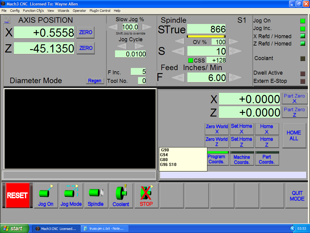
Anyway I digress - I added a screen shot of Mach3 running in constant surface speed, and I'll let you do the maths and see if I'm missing something, or if there is indeed something wrong.

Please help as it's been 3 days of headache and measuring and re measuring and taking the belt drive off to measure pulley diameters and circumfrences and maths and countless scraps of paper calculations and I seem to be no further forward :(


Pages: 1