Hello Guest it is April 24, 2024, 06:03:11 PM

Show Posts

This section allows you to view all posts made by this member. Note that you can only see posts made in areas you currently have access to.


Topics - peter.steele

Pages: 1
1
Mach4 General Discussion / Mach3 XML Reader Bug
« on: March 08, 2020, 12:33:57 AM »
This isn't going to stop me from being able to use Mach4, but it's an interesting quirk that might have caused me some setup issues if it hadn't popped up in an incredibly obvious place...

If you notice in the two screenshots below, the XML reader is getting the pin assignments in the wrong lines.

2
General Mach Discussion / Probe is triggered, but movement doesn't stop
« on: February 27, 2016, 04:31:34 PM »
Over the past couple weeks I've noticed that occasionally when I'm probing something, the light showing the probe as active comes on when it makes contact, but the machine doesn't stop moving in that direction.  This happened with increased frequency until yesterday, when it started happening every time.  This happens when probing on any axis, not just Z.  

I use Big Tex's probing screenset and also the ProbeIt wizard.  Neither has been edited.

Yes, I have limit switches, and yes, they work correctly.

I have already gone over the entire wiring setup from start to finish.  I replaced every piece of wire going to the probe, and made sure that the new wires are properly tinned and all terminal connections are tight.  None of that was the problem.  (I didn't expect it to be - the LED on screen lights up correctly, but the wires were a little ratty.)

I've already started a new profile from scratch, and it exhibits the same behavior.

I've already tried changing the probe to a different pin.  Didn't help.

I have an ESS and G540, with a SuperPID spindle controller.  Mach is version 3.043.062.  XML file is attached.

If anyone has any suggestions to offer on this one, I'd be incredibly grateful.

3
General Mach Discussion / My circles are in the wrong place?
« on: July 23, 2015, 12:09:53 PM »
So, first off, this isn't a problem with backlash.  My circles are still round, they're just ... not where they're supposed to be.  They're consistently offset by about .08 inches in -X and +Y.

For instance, in the part whose g-code I've attached below, I have zero set at the inside left corner of the fixed jaw on my vise.  I've got a piece of 1/2x6 hot rolled steel clamped up.  

I drill out the center with a 1" bit, then a 5-bolt pattern around it with a 1/2" bit.  This goes as expected.

Then things go a little abnormal.  

The next operation takes a 5/16 end mill and bores the holes out by a few thousandths for clearance, then cuts out the whole thing.  The boring operation is offset away from the center of the actual hole.  So's the cutout.  Everything is round ... it's just not centered.

This has been a problem for a while now, but I've never really done anything where the precision mattered as much as it does here so it wasn't quite as obvious.  When I saw it happening with thread milling, I figured I was stuck on stupid with something in my operation and never put any more thought into it since I was just experimenting, but it's showing up everywhere else.  If I am just milling my whole part everything's fine - the offset takes care of itself because everything is shifted ... but when I'm working with something where I have to index off an existing hole, or where I have tool changes, then there's issues.

Anyone got any ideas what's going on?

4
General Mach Discussion / Any way to ignore spindle speed commands?
« on: May 21, 2015, 01:42:48 PM »
So I've got an old Bridgeport BOSS 3 that's been converted to run under Mach.  I didn't do the conversion, I bought it already set up this way.  It runs very nicely, but there's one quirk that I don't really like, and that's the VFD.  The machine is set up so that if I set the Varidrive to 2000 RPM, the output from Mach to the VFD will have more or less the correct speeds ... but I don't get the same torque that I'd get if I just use the Varidrive.

What I've been doing is just putting values of S2000 in my programs (that gives me 60 Hz, more or less, at the VFD) and then using the Varidrive to control my actual spindle speed.  This is annoying because when I'm doing my CAM stuff (I use Autodesk Inventor HSM), I get screwy values for my SFM and chip load, plus I have to remember to manually set my speed to 2000 for every tool.  (Yes, I know I could just edit my tool library for the default value, but I haven't gotten around to it yet.)

So.

What I'd like to do is tell Mach 3 to just ignore the S command and just always give a command of 2000 RPM to the VFD.  Is there any convenient way to do this?  When I set the pulley max / min to 1999 and 2001, that doesn't seem to work - if it gets a command outside that range the spindle doesn't turn on.

Thanks in advance!

5
Okay, so what I was expecting here was a nice basic facing operation.  Climb milling with the passes along the X-axis.  .04" on the first pass, .01" on the second.

I've been using Mach for a little while now, but this is a new one on me.  Never seen this happen before.  Only thing I can think of that changed from the previous cut to this one is that I turned on backlash comp for Y and Z axes ... but this was happening in X, not in Y or Z, and I did enough testing (x0, x-1, lather-rinse-repeat several hundred times) to verify that the adjustment in backlash was returning me to 0 on the dial indicator reliably and repeatably.  Anyway, on each pass, the X zero was moving in the positive direction by something like .098", according to the DRO. (I've got one of the early Bridgeport CNC's, it still has the mechanical DRO's on it.)

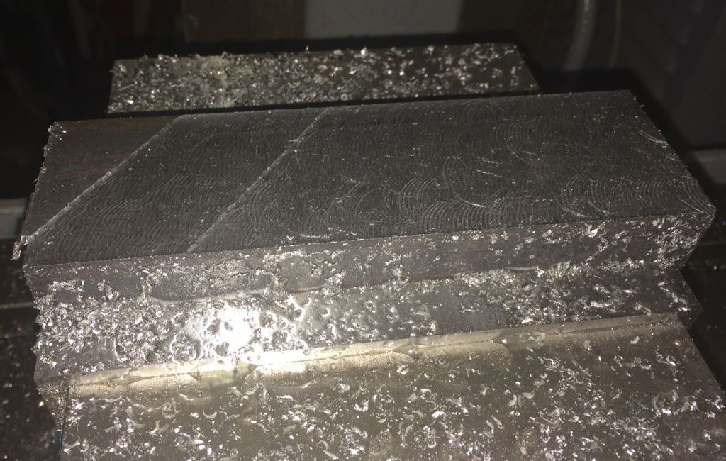
So, here's the picture.  If I can figure out how to attach a file I'll attach the XML and the gcode.

Anyone got any ideas?

(yes, I know the finish sucks - this cutter is just about worn out.  I didn't need this part to look pretty though, just be mostly flat.)


6
I'm updating the controls on an older router right now to use a Gecko G540 and Mach3, and I'm having trouble with the limit switches.

The manufacturer used NO for the Z axis and NC for the X & Y, and they're giving me fits.

Obviously I can't use NO & NC together when wired in series, so I've got each switch (all ++, used for both ++ and home on each axis) set up on a different input on my Gecko.  They're plugged into pins 1-3 on the Gecko, in order of X-Y-Z.  One wire goes to the Gecko, the other goes to the -48VDC pin on my power supply.

When I disconnect the switches and use a meter on them to check continuity, I get the expected behavior.  The Y-axis switch shows 0 ohms, and goes open when I press the button.  The Z, of course, does exactly the opposite.  When I wire them in, however, things start to go south.  The switches don't respond to anything anymore.  Automatic input setup doesn't recognize them as inputs.  I've even gone to the level of pulling the manufacturer's wiring harness and adding a new one of my own, so I know it's not the wiring.  I'm almost wondering if it's an issue at the Gecko, because even if I disconnect the switches and jumper the input to the -48VDC pin, nothing happens.  (It's unlikely to be a Gecko problem though - it's brand new.)

Anyway.  Next possible culprit is my parallel port.  If I'm not in the right mode (EPP vs ECP vs w/e), will I have LPT1 pins 11/12/13 as inputs still?  I know that pin 10 is still being used / recognized as an input.  Is there a way to tell if my LPT1 is set to the right mode?  (My BIOS doesn't show the info - my only options there are enable & disable.)  Computer is a Gateway E4300 running Windows XP SP3.


Thanks ...


7
I have a router made by Vision, with a Series II controller.  The controller as it sits now only accepts HPGL from a proprietary software supplied by Vision.  (I have it, but I don't like it - I want to do 3D work, so I'm attempting to retrofit it to work with Mach3.)

I've opened up the controller and isolated all the inputs / outputs that I need, except for the limit switches.  The steppers are driven by IM483 boards, which are quite well documented and I'm not finding many particular issues there.  I'll take STEP / DIR from each of the 4 to pins on a new DB25 connector that I'm adding to the housing, while leaving +5V connected to the existing controller.  I'm not bothering with a BOB here, as the drivers are fully opto-isolated, and they're still being powered by the PSU inside the controller.

Now the question I have about the drivers is the ENABLE pin.  It's currently being driven by the controller.  Should I leave it there, or connect it to the DB25 and drive it through Mach?  I'm guessing that this will kill the steppers when the E-stop is active?

Next question: the E-stop itself.  The controller has a 2-wire e-stop.  I'd like to keep it connected to the controller, as that will still be powering my spindle(s), dust collector, steppers, etc.    Can I simply take a tap off one leg of the e-stop wire (probably the black one) and run that to one of the input pins, and set that one as active-high in Mach3?  I guess the same question applies for the limit switches ...

8
There's not a whole lot of information out there on this.

I've acquired a Vision 2448 router / engraver.  It's got a proprietary control panel setup (series II, with serial connection) which doesn't seem to be friendly to anything other than their own software, which doesn't seem to be really useful for what I want to do with it, which is 3D stuff.

Anyway.  The controller has a 25-pin connector to the table, and separate cables heading to the spindles.  Anyone ever tried to figure out the pin outs for the table on a Vision router to drive the table with Mach3?

Pages: 1