Hello Guest it is May 05, 2024, 03:07:39 AM

Show Posts

This section allows you to view all posts made by this member. Note that you can only see posts made in areas you currently have access to.


Messages - simpson36

421
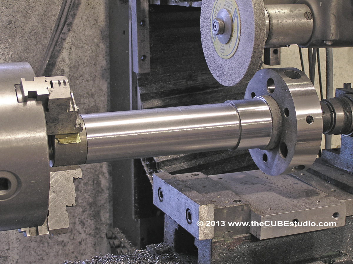
I think that to run higher than about 8k to 10k, it would be advantageous to have an extremely rigid spindle. This will be much more resistant to harmonics. I made a spindle  using A6 tool steel. Properly hardened and tempered and fully ground, it will undergo torture testing in my InTurn™ 4th axis. Obviously, I will not be running the 4th axis at 15K RPM, but it is a brute and quite capable of testing the strength and rigidity of the new spindle. Once I am confident of its performance, I will make a similar one for the upcoming high speed BT30.


422
A detail I don't think I covered previously. If I did, then sorry for repetition here:

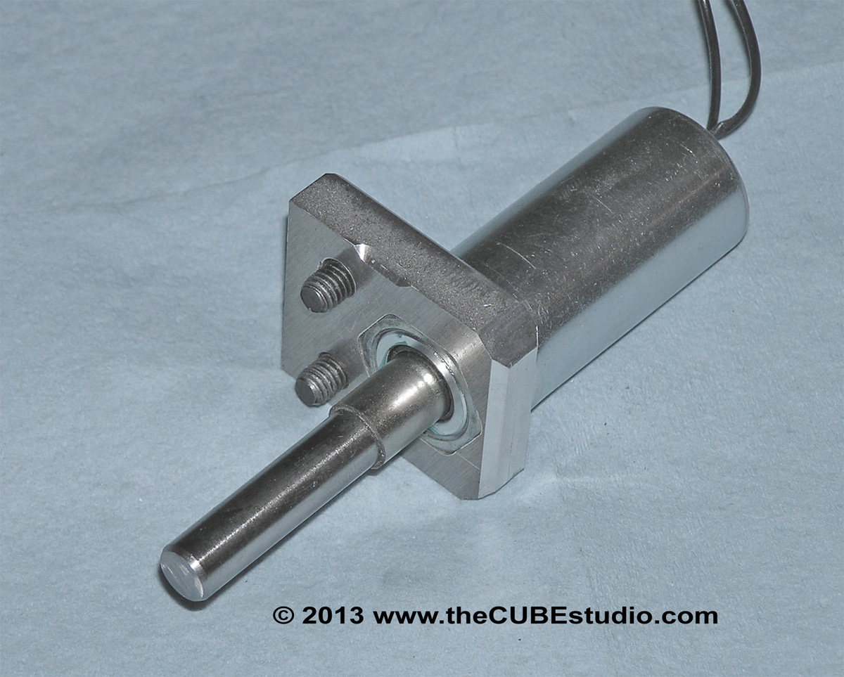
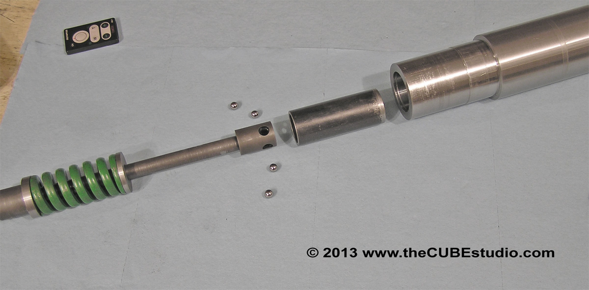
What I consider to be THE most important part of the whole device is this little guy. The pin is hardened steel and rides in a hardened die bushing in the drawbar actuator. This pin protrudes from the bushing and provided a positive mechanical interference with the actuator's operation. In other words, the spindle CANNOT release a tool unless this solenoid is first activated removing the interference. The actuator has some serious Kahunas, so the hardened components used here are so that the interlock can get more than one use.  :P


423
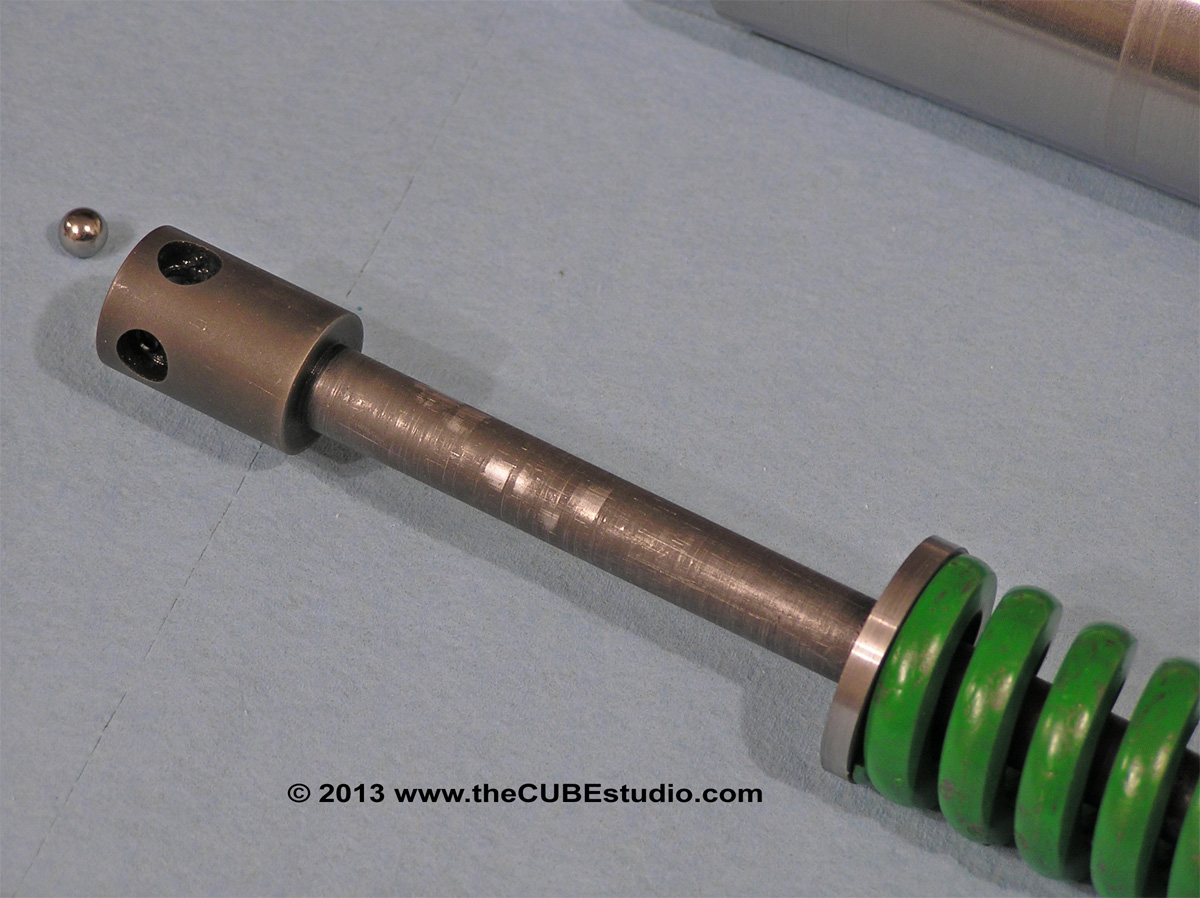
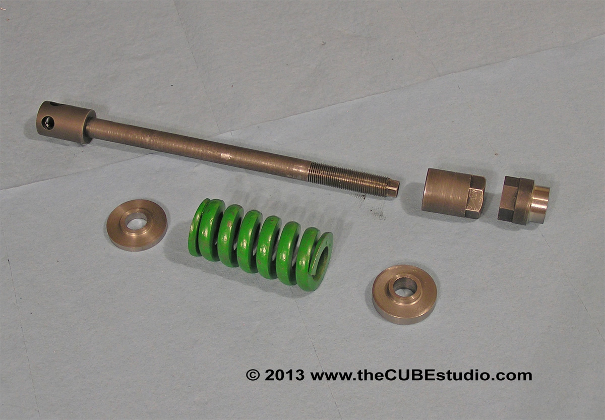
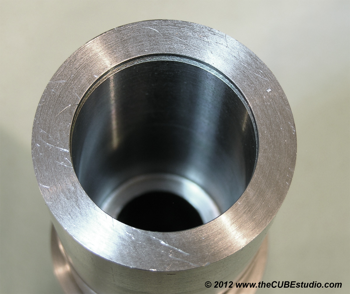
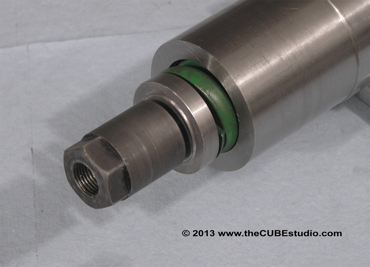
I'm going to back track a bit now. I don't think I covered this well, and there are questions so here is the story on the 'big spring'. The photos are self explanatory for the most part. The spring is held at center by the washers above and below the spring. The smooth bore for the spring pocket is to allow the spring retention washers to slide smoothly. The spring itself does not rely on the bore for centering. In fact is does not touch the bore at all:

 Belleville chafing problem is evident on the first photo. The bar gets an initial compression and is retained by a snap ring in the top of the spring pocket. This has a side benefit in preventing the bar from extending up and pressing against the actuator when there is not tool int eh spindle nose.


424
OK, here we go . .  finally.
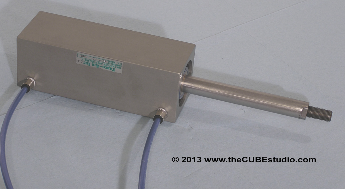
Air cylinder speed is a topic, so I'll start with some mods to the arm raise/lower actuator cylinder. When I removed the restrictor, I found it actually did not move as fast as I wanted, so I had to take it apart and drill the air passages a bit larger and use 1/4" tubing. Fortunately there are 1/4" tube x 1/8" NPT fittings so I di not have to drill and re-tap the ports. It's plenty perky now.

Not so exiting photo here (don't worry it gets a lot better in the next couple posts):


425
Steve,

Thinking about it some more, I think a solenoid-controlled needle valve driven by a simple (even software) PWM would be the way to go.  Simple to implement, and should give very good control.

Regards,
Ray L.

Right on the money, as usual. The trick is to find something 'off the shelf'. I'm thinking there must be a computer controllable (PWM, analog, or whatever) orifice or regulator. Hopefully there are some industrial control gurus lurking around here that can provide an example.

In hydraulics, you get electrically controlled variable flow control valves, and I'd guess someone will do something similar for air.
However the usual way for controlling cylinder speed with air is by controlling how quickly air escapes from the non-powered side of the cylinder. The flow restrictors are usually plumbed in with a one way valve, so you get full flow into the cylinder, but any flow out goes through the restrictor.

Exactly correct, however, the objective is to find a computer controlled restrictor. Must be something out there. I'm just being lazy really  . . don't want to do the research  :-[

426
OK, I think I have answered all of the questions. Couple general comments;

* Not interested in introducing hydraulics.

* PWM out and analog in and out are standard feature of the current crop of tiny processors so extra boards are not needed.

*Anything that requires operator intervention is contrary to the design goals here.

* cost is always a consideration except where safety is concerned, but it is not high on the menu here as this device is not intended for hobbyists . . per se.

* Bang-bang is not the concern and is easily handled by cushions built into the cylinders. It is a standard option with Fabco, for example.

* fixed speed control of the air cylinders id not a concern as that is easily accomplished with available adjustable orifice valves specifically for that purpose. I have one of those on the drawbar actuator in the 'grip' direction to reduce the shock load on the gripper. Shock load is beneficial and perhaps even needed on the release cycle, so there is a small acceleration gap and no restricts.

* the challenge is to be able to computer control the speed of the air cylinder that raises and lowers the arm.  Given that for any specific part, the overall thoughput can be significantly effected by optimizing each operation, it makes sense to run the ATC as fast as possible with small low mass tools and slow down for very heavy or large tools. I have read volumes of concerns over drawbar release pressue being taken by the spindle bearings, but in most cases that is really a needless worry as the static load on the bearings is typically far above the drawbar pressure. However, taking a very heavy tool and slamming it into the spindle taper is not a good plan. Note that industrial robotic loader/unloader mechanisms almost always decel just off the target and gently deliver the load.


427

Simpson better get cracking on his ATC! I'm already working on my second one, for my new machine!

Regards,
Ray L.

Hey, haven't you won this thing yet? I caught you sand bagging one sensor as I recall. Is that done?

428
Hey Steve,

Having said the above, another way, but more expensive, is to drive the entire contraption via PLC brain, you could use "High Speed counters" or Stepper/motion cards to drive or read, or drive/read your motors.  You can use inexpensive AC or DC motors, and put an Encoder on the motor or on the moving part, your choice, and read its distance via the High speed counter,  you can set all kinds of very good positioning that way. The next level up would be stepper (or servos), controlled via a motion card on the PLC (with Encoder feed back). Many of these cards you can select various "Motion Profiles" and set up motion/velocity tables, with set positions that can be called. (this applies to both linear and rotary motion).

I have a pair of Mitsu servo motors actuating the carousel and the arm. The whole thing is controlled by a processor running C code. After thinking about Hood's excellent suggestions, I reasoned that writing some code to generate a step stream and run the servo drives would be shorted time-wise than the learning curve for a new type of industrial drive. The AB seems quite a lot more intuitive that the Mitsu, which is extremely complicated to use in that way, but the code to run the drives was relatively simple and I have the carousel routines finished and tested. The arm is the same servo drive (just a newer model) so the same code, slightly modified will do that job as well.

Ultimately I am thinking about following HimyKabibble's lead in implementing a Kflop and connecting 'satellite' task specific processors to it, but that's a big meal that I don'thave time for at the moment, so I elected to pile the ATC code on top of my existing InTurn™ 4th axis motor controller since it is already tied in and talking to MACH. The little processor has it's hands full as it is, but a tool change happens 'in a vacuum' so to speak when everything else is on hold, so it will probably be fine.

Quote
IF your real, real hell bent for leather, then you could just use analog cards, with linear rheostat for feed back coupled with a PID loop per motion axis/device...
Many, Many ways to kill that cat, even do PID loops in a plugin if you like the pain....

Scott

Running in the dark .  with scissors . . and my hair on fire . .  is pretty much normal condition for me . .
429
Hey Steve,
 
Also:  Having built a Prototype ATC, I would NOT try and use "Air Cylinders" for any type of speed control. It is very hard to get the flow valves right, and the instant that your pressure, or humidity changes at the source, then those speeds are not longer valid........ Other than Bang-Bang motion, they are not good velocity or positioning devices.  It would probably make MUCH more sense to do a Rack/Pinion or acme screw/nut for linear motion.

Scott

I have to agree with you from the aspect of control. While I was noodling around on ways to power the various actuators, I discarded rack and pinion because of the difficulty in keeping it clean. The environment is difficult because of the flying swarf, coolant, etc. My career was primarily fault analysis on mechanisms in industrial environments, so I am always thinking in terms of 'what would happen if someone shoveled gravel into this machine' .  :o


430
Steve,

Thinking about it some more, I think a solenoid-controlled needle valve driven by a simple (even software) PWM would be the way to go.  Simple to implement, and should give very good control.

Regards,
Ray L.

Right on the money, as usual. The trick is to find something 'off the shelf'. I'm thinking there must be a computer controllable (PWM, analog, or whatever) orifice or regulator. Hopefully there are some industrial control gurus lurking around here that can provide an example.