Hello Guest it is May 05, 2024, 07:05:12 AM

Show Posts

This section allows you to view all posts made by this member. Note that you can only see posts made in areas you currently have access to.


Messages - simpson36

391
Here is the head in its current condition. Actuator is not on the head in this shot. The motor pulleys are large diameter because if they were smaller, the tension would exceed the belt spec . .  even with 1" wide belts. That's a Big A$$ Motor.

Dual speed ranges are 1:1 and 2:1   MAX spindle continuous is 6,000 RPM with 'instant' speed of 7,000PM. 


392
Typically I do not do 'conversions' but I have been busy building a CNC mill using the castings from a  new IH mill for one of my 4th axis buyers who also purchased the second prototype BT30 spindle, Drawbar actuator and the prototype ATC. This machine is 5 axis and has 8 servo motors.

One of the reasons I agreed to do this project was that it seemed feasible to come out the other side with a CNC retrofit 'kit' for this largest of the  'off-shore' square column bench mills. However, shoe-horning large precision ground pre-loaded (large ball nuts)  ball screws into this machine (even though it it the largest of its type) required so much machining of the castings that it became obvious that this is not a candidate for a DIY project. The IH column is open in the front so it had to be boxed in and linear guides were used in place of the dovetails.

I committed to this project so it will be completed, and it is an excellent platform for the BT30 spindle and ATC, but there will be no retrofit kit for the IH mill and this will be a one-time deal.

There have been no postings here because the progress so far did not involve the BT30 spindle, drawbar actuator or ATC, but that's about to change as the head is now completed and the BT30 spindle detailed in this thread (the second one actually) is now running. The owner chose a huge spindle motor for this machine which caused a lot of problems and required a lot of re-design of the head and drive components. That slowed progress considerably, but it's finally all completed and running.

Here are the videos covering progress on this project, axis by axis. The next video will cover the all new head which contains the BT30 spindle, drawbar actuator and ATC. The spindle motor is a 3,500 watt Mitsubishi AC servo running on three phase power. This next video should be up in a few days. The project wraps up in a few weeks when the owner comes to collect his new 5 axis toy.

http://www.youtube.com/watch?v=20l-HVgJtcc
http://www.youtube.com/watch?v=_sH8nBUxIV8
http://www.youtube.com/watch?v=b812wagyBW0


393
Steve,

Looks good, but needs more wires!  :-)  You know Craig has his Bobs ready?  I got my two a few days ago - they look really nice.


I was already pretty far along with the wiring diagram by the time the BOB was ready.  I had made a career out of this task already and was well into modifying the interface boards (to not instantly fry the K-flop's 3.3V 10mA pins) so the last thing I wanted was to rewind to add a new piece to the puzzle.

Craig had to make some decisions about I vs O and I would need to really compare his choices to my needs and see if there was enough of each flavor. On this project, there is a LOT of I/O and having a bunch of them pre-defined *might* present a problem, but I'll peek at that issue for the next project. I also need differential signals and relays that can drive coils and 24V isolated stuff and on and on blah blah blah, so if I decide to stay with the K-flop, most likely I will make my own BOB with all that stuff on it already. The incomprehensible tangle of individual wires is definitely a huge attraction, but alas we must occasionally yield to practicality  ::)

Certainly the BOB would be a big help to anybody doing a *typical* MACH install with 3 axis of single ended signals.

Quote
What connectors did you use to connect to the KFlop?  I've never seen any like that.


The connectors are just the mating parts for what is on the K-flop. I chose to use crimp pins for flexibility (read: fixing screw-ups). I prefer to use color codes and heavier wire than is available in ribbon.


394
I have been working on the control side of things so there is not much to report on the hardware. As I mentioned earlier, the control scheme is really the more difficult part of the ATC project. The prototypes in this thread are being incorporated into an all new CNC converted IH milling machine and the controls will have the ATC fully integrated. I will only be posting here  the portions of that project that are directly related to the BT30 spindle and the ATC.

To that end, I have just completed the computer, motion control setup and interfacing for the project. On Ray's recommendation, I went with the K-flop board over the smoothstepper. While the Kflop board is far from the 'plug and play' that I was hoping for, eventually (with very prompt, accurate and well targeted support from Dynomotion on their Yahoo group) I did get it going. A major caveat with the K-flop is that 'most' of it is 3.3V only. I got caught with my pants down on this because I only read the K-flop spec to the point where it said '5V tolerant', however, when I went to integrate the board and read the entire spec, I discovered that only a few of the pins are 5V tolerant and the rest are 3.3V ONLY, which was bad enough, but they also are limited to a tiny 10mA current. I now have 7 different boards and many of them had to be redesigned to work with the K-flop, and I had to make up a special batch of boards for this project . .  a rather large task that I had not anticipated.   :'(
 
Although there is essentially zero cutting time on the system, so far it has not exhibited the USB smoothstepper's bad manners, so I am encouraged that it will be a good solution for the initial MACH3 support as well as hosting some or all of the ATC control in the future. The K-flop is running a total of 7 axis; 3 linear, 3 rotary and the servo powered spindle.

At this time, my InTurn™ 4th axis motor controller is hosting the ATC controls. The motor controller has a multi task board (swapaxis, digital signal synthesizer, line driver) that is mounted in the CNC computer so for the sake of simplifying the external cabling, I ran all of the controllers cables to the CNC computer. From that central point, all of the cabling runs to two large enclosures which house the EIGHT Mitsubishi AC servo drives and a bank of 12 relays. From the enclosures, one set of cables goes to the head and include the spindle servo cables, the ATC cables and all sensor cables. The second enclosure has a set of cables that run to the mill base and contain the X,Y, and Z axis, the InTurn™ 4th axis, 5th axis servo cabling as well as relay and sensor cables.

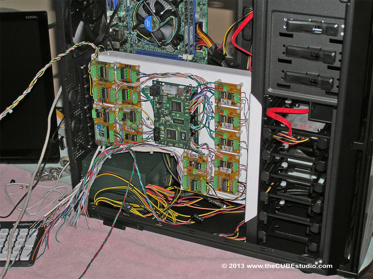
The first step in the overall task is now completed. I fabricated an aluminium 'mezzanine' plate to mount the motion control board and all of the supporting interface boards. This is mounted in a large server case with the dozens of wires collected into SIX connectors on the back of the case. In the planned arrangement, the computer will be on or near the floor with approx 6 feet and 10 feet cable runs to the two wall mounted drive enclosures. Cable runs from the enclosures to the mill will be 8 to 10 feet. All of the servo cables are Mitsubishi factory made parts. Pneumatic valves and mechanical solenoids run at 12V and the optical sensors and limit switches run at 24V to help with noise immunity.

I am very happy to have the electronics portion (which I do not enjoy) completed so that I can now move on the the mechanics of the conversion (which is the fun stuff).  

This is the mezzanine with all of the goodies installed and wired up, but without the external connectors


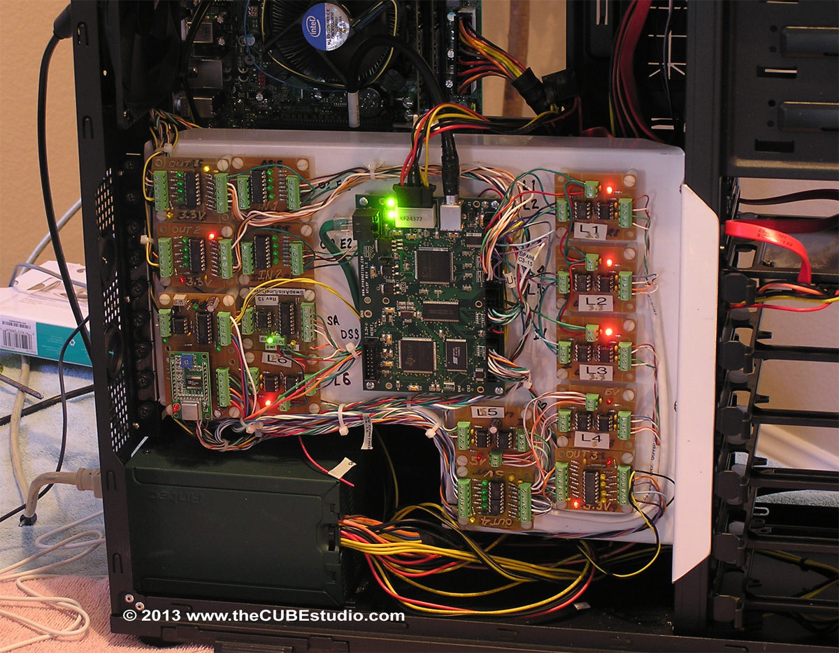
Next is the completed setup final install and running


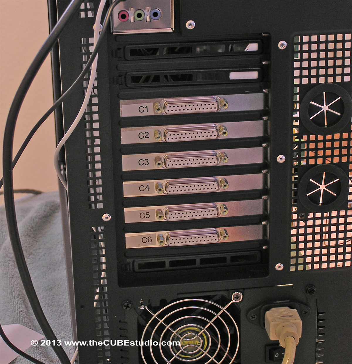
This is the back of the server case showing the 6 DB25 connectors needed to get all of the wires where they are going.


395
Progress is creeping along on finishing up the ATC. The last tasks are to put the sensors on the various parts that I want to monitor. Sensing the vertical position of
the arm proved to be a vexing problem, but the solution to that dilemma also provided improvements on some other aspects of the actuator that I was not completely satisfied with.

The photo below shows the new cylinder mount. Previously the cylinder mounted to the head on a heavy bracket. This required very close alignment to prevent the shaft from binding as is slides thru the gearbox. This new arrangement eliminates that separate mount by attaching directly to the gearbox. This not only guarantees alignment, it also provided for a single attachment point to the head and completely encloses the shaft. The cylinder has a magnetic piston and the position is readable by external adjustable sensors as shown in the photo. There will be a second sensor at the top of the cylinder to read the 'UP' condition. The shaft below the gearbox will be covered by a corrugated rubber bellows.

The cylinder pictured was intended to be only temporary and for feasibility and testing, but the performance seems perfectly adequate, so at this point I am inclined to leave it in place.

There was a question earlier about the shaft 'slamming' at the end of its travel. This cylinder has internal rubber bumpers at each end of the stroke that cushion the sudden stop. The air inlet and outlet fittings on the cylinder have needle valve adjustment for flow, so the speed (although not the force) can be adjusted.

I am very well pleased with this arrangement and will be duplicating the magnetic sensing method on the pod tool release cylinder as well. It is an expensive solution, but one that will prove reliable in a difficult environment.

There remains only one interlock and associated sensors for the tool pod release function. . . . and make 4 more tool pods for the carousel. Most likely I will use a solenoid actuator and optical sensor in this case.

I will post a picture of that last interlock when it is finished and that will complete the mechanics of the ATC, leaving the most complicated task of the whole project; the control software . .  which I would say is about half done. I'll make another video of the testing once these last tasks are completed . .  no ETA on that.


396
I do have a untested yaskawa servo drive under the bench that I may break out if nessessary it is supposed to drive a 5HP spindle I was sort of holding that back for a lathe project but who knows.

archie =) =) =)

 ??? Your 4th axis project IS a lathe project. Once you have your 4th axis doing turning on your mill, as Scarface would say "I don need no steenkeen LATHE!"

Yaskawa AC drive would be an excellent choice. If you have 5HP (continuous), you might get away without dual range belts, depending on the type of work you are doing.

397
Is it just that the changeover is slow. or is it a programming  issue  IE having to massage the code by hand.

Thank You
archie =) =) =)

I'm not sure what you are asking here. There is a feature in MACH called 'swapaxis' that can be used alternately connect the spindle axis and the A axis to your 4th axis. I used that initially and then later created a small circuit board to accomplish the same feature in hardware. Either method is essentially instantaneous. There are some caveats to using the internal MACH command which I think are detailed elsewhere in this thread.

You have to message the code in any case, so that is not a factor in deciding how to control your 4th axis motor.  On that topic, a couple of my buyers are working on post processors that embed the codes for the InTurn™ and there are three editors that make it quick and easy to embed the codes.

*The most sophisticated is an editor by CNCcookbook. Bob Warfield added a feature for the InTurn™ (or equiv) code 'massaging' that that actually looks at the context of the G-code and can differentiate where a command should be embedded and where it is should not. A 'smart' editor, if you will.

*There is free editor called NotePad ++ that has the ability to replace a line with several lines. This is the 'secret' to fast and easy editing to add InTurn™ commands.

*A third CNC code editor has promised to add a similar feature, but so far I have not heard back from them and I have not gone searching to see if it is done yet.


398
Yes that was the two questions and you have answered them. I will be making a balancer at some point.
 
I would  to do this from inside mach3    I want a true 4th axis ( as a
indexer and a spindle with brake) to run on my bridgeport R2E4. I have
no requirement to have separate electronic box to control the 4th axis. while mounted on the cnc mill.
understanding  I want this for my own use.

thank you for the help
archie =) =) =)

The control box turns over control to MACH for indexing, so when in INDEX mode, it operates as you describe, i.e. within MACH3.  MACH has no ability to continuously rotate an axis so you will need to do some 'smoke and mirrors' tricks to get that to happen. There are a couple of ways to go about it and I think those are detailed early on in this thread. I was doing the INdexing TURNing using MACH only for quite some time before I made the control box. It is doable, just a bit inconvenient and limited. It is a good place to start. If the limitations become a problem, you can then create a separate controller for the TURNING operations.

Lack of enable/disable is a serious handicap. Cost condiserations may force the use of a hobby drive to get started, but the more you use the machine, the higher the priority will be to upgrade the drive.

399
An Atmel processor (on an Arduino MEGA development board) is used for data acquisition only and the data (sensor reads) that is collected on each run is sent over a serial connection to a program on the PC for the calculations.

Is it a commercial program or some code of your own?

Dan

My own.

400
all I can say is wow I have read the thread backward and forward. everything is unbelievably well documented  except the balancer it looks home built as well. I am very interested in the harmonic balancer

I think you are referring to the dynamic balancer. Yes, it is a 'home brew' machine. I wanted to purchase a commercial balancer, and I still may at some point, but the machines are just way, way too expensive to justify at this point. I am able to do an acceptable balance with my balancer, it just takes longer . .  a lot longer actually. However the end result is similar. Having a spindle balanced at a commersial shop runs between $200 to $250 for the level needed by a 4th axis.

For liability reasons,  I do not release any information about the balancer, and I do not sell them. It is going thru a rebuild and upgrade right now to increase its balance speed from 4k RPM (InTurn™ 4th axis ) to 8K RPM (new BT30 spindle).

What I can do is describe the basic operation using a broad brush and you would need to take it from there.

1) A 'floating' carriage holds the item to be balanced
2) when the item is spun, the carriage oscillates as a result of the imbalance
3) a sensor, either pressure or accelerometer, records the movements while an absolute encode simultaneously records the azimuth.
4) Software calculates the amount and position of the imbalance.
5) the item rotation is stopped and the item is turned by hand to the exact imbalance point as shown by the controller.
6) weight is added to the light side or taken off the heavy side and the process is repeated.

An Atmel processor (on an Arduino MEGA development board) is used for data acquisition only and the data (sensor reads) that is collected on each run is sent over a serial connection to a program on the PC for the calculations.

My upgrade of the balancer involved beefing up the floating carriage and swapping out the current 16bit 16MHz processor (Arduino MEGA) for the new 32 bit 84MHz Atmel processor (Arduino DUE)  which is 4 to 5 times faster and moving from analog to digital accelerometer. Hopefully these improvements will allow fast enough data collection for an 8K RPM balance.

I hope this is of some help to you