Hello Guest it is May 05, 2024, 12:50:12 PM

Show Posts

This section allows you to view all posts made by this member. Note that you can only see posts made in areas you currently have access to.


Messages - simpson36

591
Short update; with my new 'Mega' 4th axis project completed, I am turning my attention not to completing this BT30 spindle for my new mill.

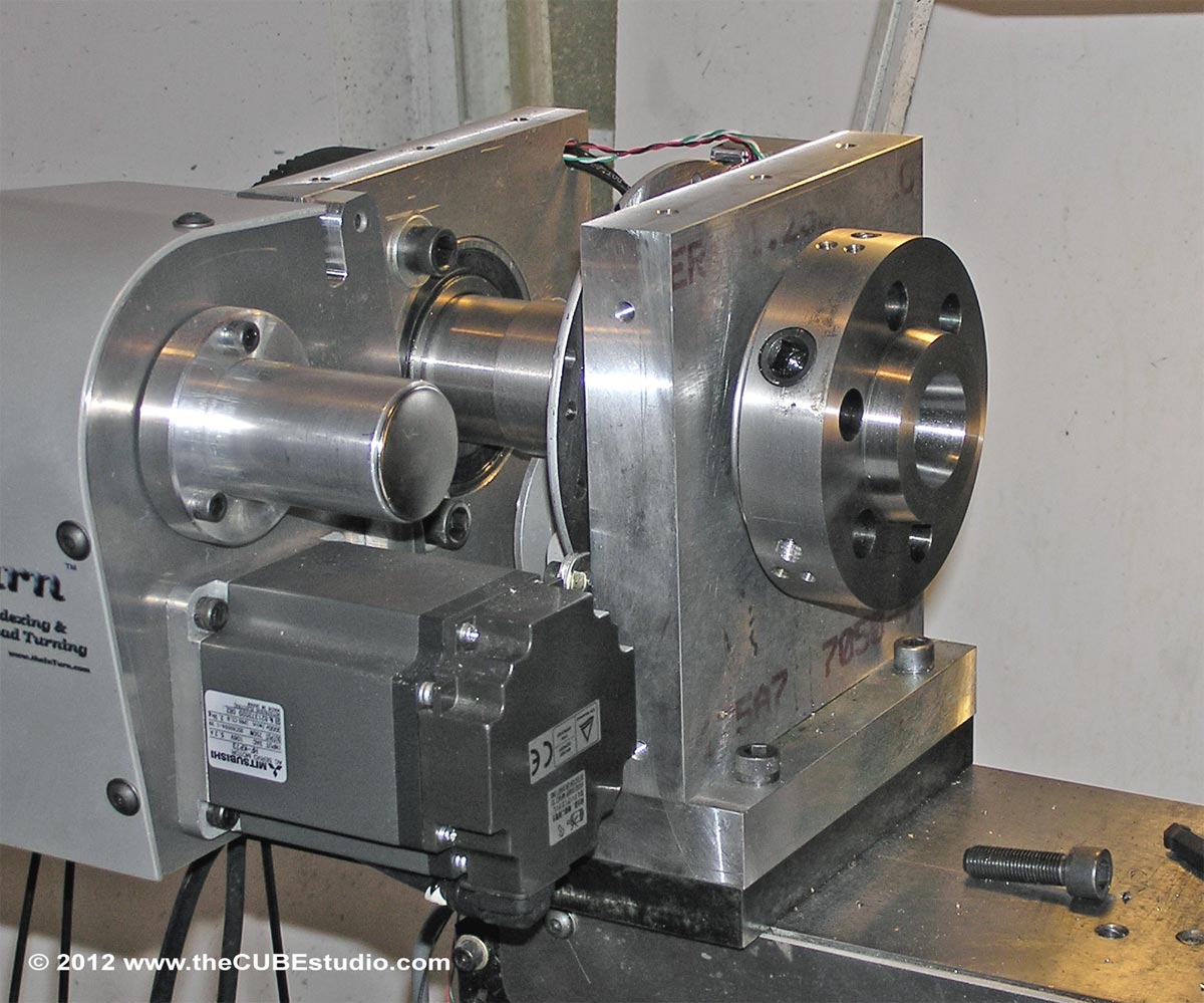
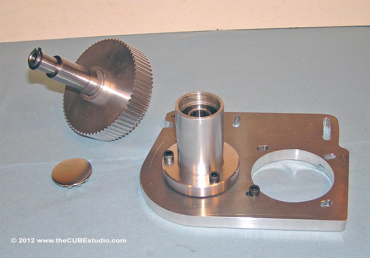
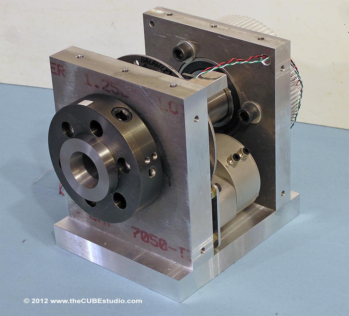
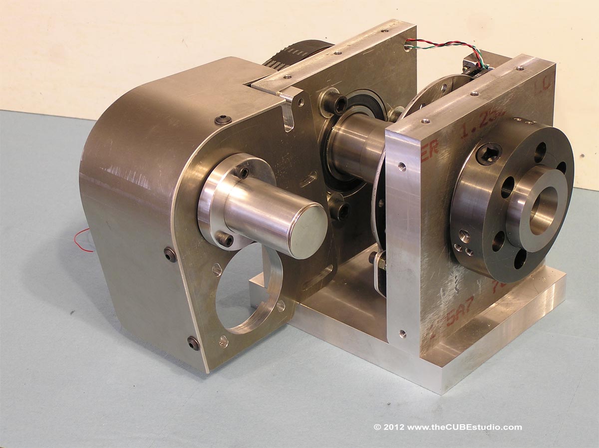
Two things became apparent while building the new D1-4 Cam loc spindle for the 'Mega Duty' 4th axis; 1) more power was needed to drive the 1" drill bit thru hard material and 2) the mill column would need to be reinforced and welded up to resist twisting during the drilling operation.

The previous 4th axis prototype had only slightly less torque than needed for the 1" drill thru. The previous 'Super Duty' had just under 6:1 reduction and the new 'Mega Duty' has 12:1, so I am not anticipating any problems at all with the drilling. I have taken down the mill column and boxed it in with 1/2" 1018 CR plate and welded it up. The column should no longer get twisted by the drilling force. The mods should allow the pre-hardened material to be drilled thru the entire 9" length from one side at 1" diameter. The material will be here tomorrow.

I had hoped top avoid the big hole by using a coil spring. This would require only a hole large enough for the rod, but when I went back to complete the spindle design, I found that this was not going to be possible for BT30 because of the small size of the adapters. I think it may be doable in the larger sizes, but I have not looked at that. I considered briefly moving to a larger size, but decided against that solution. Therefor I will be using the dreaded belleville spring stack for this first spindle due to the small adapter size. That is the situation, even though it does not sound particularly logical.

592
Yes, the new 'Mega 4th Axis' has the Servo motor from the previous prototype. It is now installed and has begun its working life.  The last steps were to to drill the base, drill a couple of additional holes in the outrigger plate (the 'Mega' is longer), align the machine, do the final cuts on the tapers with the machine installed and under its own power, mount the D1-4 Chuck adapter and then cut and final grind to mount the 6" Bison chuck. I also now have a balanced 12" cast iron D1-4 mount face plate.  You can see that piece and also build details and install details in an upcoming video.

Here are a couple of selected final shots to finish the update to the thread. First is the in-place cut of the tapers:


Next is a shot of the ground cam-loc face of the completed D1-4 chuck adapter:


THe completed adapter is then installed on the re-cut spindle and then rough cut and ground to receive the chuck:


And lastly a glamor shot of the finished product . . .  which I will have to do over because it had not occurred to me to wait until the spindle was final cut:


593
Project is just about completed. This new machine will be operational in a day or two and the current 4th axis prototype is now for sale if anyone is interested. It is the machine making the parts for this new prototype and in the latest videos. PM me for details.

A couple of interesting componenets are the belt tracking adjuster built into the counter shaft housing. The housing is mounted via a ball socket and can be angled a couple of degrees by alternate tightening of the flange bolts to effect belt tracking.


Looks like this assembled:


Balanced main drive pulley and hub. Note the drilled holes in the hub for balancing. In this close up, you can see the super straight teeth afforded by the spindle lock.


Some 'undressed' shots of the finished new 4th axis are next. The new 'Mega' 4th axis has pretty covers with the name imprinted on them, but I do not have photos of that yet.


594
I'm cobbing up a quick 6 position tray type holder and I'll auto tool changing!

What are you using to hold the BT30 adapters in yout tool tray?

595
Derek, thanks for the replay. What you have is exactly what I was referring to in that you have a much smaller stack of much larger springs. Your stack is under 3" and arranged on top of the spindle instead of being 12" long and extending thru the spindle. Very good to have a working confirmation of my theory.

Coincidentally, I was slogging thru some numbers on the BV springs here this morning on similar springs and your selection produces the best numbers I have so far. Great choice!

Your finding without the dogs also reinforces the 600# spec I have for under 6k. drawbar tension. That test needed only a torque wrench to be 'scientific'.  

There was a comment about re-venting the wheel which I have pondered further. It occurs to me that if BV had some distinct advantage over coils, valve springs would have been replaced long ago. Now strictly to speculate; it seems to me that based on the manner in which Bellvilles flex, they would have a very short fatigue life. That notion is reinforced by another comment about the frequency of replacement, however, by primary objection is the containment issue which is made more complicated by the BV spring OD changing as it flexes.

596
I already mentioned that the spring would be in a pocket machined in the top of the spindle and and held by a valve spring keeper. I would thread the top of the rod and run threaded nut/flange down onto the valve keeper so there is no need for a spring compres or at all and adjustability would be provided simply by turning that nut/flange. The spring pressure could actually be measured/monitored  by the air cylinder, but that's another topic.

If everything was done 'the way they always have been done', we would still be riding horses to work every day . .  or worse . . . we'd still be lion food. Edison said something like "I have not failed, I have simply  eliminated 10,000 material candidates so far" . Education, experiece, research . . only take you so far, and eventually, like the movie says, you just gotta go 'WTF' and give it a try.

One of my favorite sayings, which I had framed in my offices years ago was "A ship is safe in port, but that is not what ships are built for." But I digress . . .

http://www.summitracing.com/parts/SCC-SRP1363-1/Application/?prefilter=1

This guy seems like a perfect candidate. This spring exceeds the spec. I am leaning this way unless a 'game changer' that I have not though of comes up. I am not concerned with easily solvable retention or installation issues. This spring would only need to be compressed about an inch. I have not done the math on a belleville stack so I don't know at this point how much you would need to compress that stack, but the inch or so required by the coil spring is acceptable in my view. Changing to a lighter or heavier coil spring or replacing the spring would be very simple. The stack designes I have seen so far have no provision for changing the stack without removing the spindle and I am not keen on that idea. I am performance oriented and if the coil arrangement will perform with out the disadvantages of a long stack of springs, then I would be inclined to look at it more carefully. I have more to learn about this, but you guys have been a big help, and I appreciate all of the comments.

Thanks everyone!

597
Thanks again for the replies.

I had not considered the disc-to-disc friction on the Bellevilles . . .  certainly a consideration.

Although in the final analysis it may be the only workable solution, the whole belleville stack idea just does not appeal to me. Is there some reason that, considering the small size of the BT30, one could not use a valve spring. Not from Grandma's Chevy, but a racing spring or a diesel spring.  I have not looked at diesel springs yet, but Racing Valve springs are available at 750lb rate with over 1,100lb open pressure and 1" travel. These are meant for about 350lb seat pressure, but the gripper needs only about .23" movement to release so that would leave .77" compression on the spring for about 750*.77 + 350 or approx 930lbs constant pressure and 1,100lbs max at full release. This seems doable with a pocket in the top of the spindle to center the spring and just using the racing spring retainer that would normally be used with the spring.

The relatively small diameter and mass of the coil spring being held at center I do not *think* would pose a balance problem, but the spindle would be balanced anyway, so that's not a concern.  At that high compression, the coil would loose tension over time, but I would wager it would be an improvement over replacing bellevilles twice a year.

Reliable, predictable, balanced, frictionless linear pressure. For the little BT30, it seems very doable. Have I missed another bole in the logic?


598
You can never have TOO much drawbar tension(;-). But you do have to consider design parameters. A real pull stud(stud only) is designed for up in the neighborhood of  100,000 lbs of drawbar pressure before failure. The upper end level depends on the material and design used before the stud stretches or the drawbar stretches and releases the pressure and the tool holder.

An interesting statement considering the range of sizes these things have. My calculator has you off by an order of magnitude for the cross section of a BT30 stud . . . and that would be with a zero safety factor. This is one for the 'agree to disagree' file.

Quote

The other side of the design is releasing the high drawbar pressure. Also fitting in the Very TALL spring stack as high pressure calls for a very tall stack to get pressure and overall travel.

The overal weakness of MOST power drawbar systems is the SPRINGS that retain the pressure. The more you use them the sooner they loose tension or Break springs. Not unusual to change out stacks twice a year on 24/7 machines .


Working with only  'Catalog knowledge' of Belleville springs, and having no resources to draw from, I am in WAG mode for this aspect of the design. I am aware of the tall stacks of springs. I was thinking the travel could be had by simply using a few large diameter springs at the top of the spindle rather than a long stack of small diameter springs inside the spindle. However, I have only seen the guts of a couple of spindles, and so far none have taken this approach. Have to wonder why.  Other than redundancy, it is hard to find a major advantage to the tall stack.  It there a hole in this logic?


599
The current limit resistor is switched by a relay.

I am aware of the resistor set power limits, but a couple of your descriptions lead me to believe you were changing the force in real time. Some of the industrial drives have commandable parameters that can be set 'on-the-fly', but I recall that you were using Gecko (or equiv), which do not have this capability, so I suspected that you had something more up your sleeve. 

Relay switched resistors . .  very clever indeed.  8)

600
Just a thought, (;- )TP
Your thoughts are always interesting and welcome. What I am hearing is that there are a lot of practical examples to consider. It all boils down to 'where the rubber hits the road' or in context; 'where the tool hits the workpiece'. Everything before and after is academic.

7HP is peak, so I have to design for that amount of power, even though it is momentary. Chiploads would be calculated on continuous power, which is considerably less. The motor is rated in the neighborhood of 7 amp cont. 

The question of drawbar tension is also academic with regard to 'how much is enough', so why not just go high and 'play it safe'? Once again there are practical considerations, in this mechanism there is a 'jesus nut' which is the pull stud. These little guys are stupidly expensive in spite of the tiny bit of material and very simple geometry. The cost is in the testing of each part. Fatigue life is probably too big a topic for a hobby forum, but suffice to say that any metal part that is repeatedly stressed and then released has a fatigue life. Airframes are retired after a certain number of hours for that reason and so *should* pull studs.  The relationship between the amount of stress and fatigue life is not linear.

An analogy that most reader can identify with is fuel consumption. If you drive 60 instead of 50, you might expect to use 20% more fuel for the 20% increase in velocity, but that's not the case. And the delta in fuel consumption between 50 and 60 is not the same as between 90 and 100, even though the delta in speed is the same. Travelling at very high speed has benefits and costs associated with those benefits. There is a lot of focus on 'too low' drawbar tention, but there is also a 'too high' drawbar tension which ultimately can do much more harm.

Just a thought back at ya, (;- )   SS