Hello Guest it is April 18, 2024, 01:50:52 PM

Author Topic: A Wee Prober  (Read 15854 times)

0 Members and 1 Guest are viewing this topic.

Offline mc

*
  •  382 382
    • View Profile
A Wee Prober
« on: July 30, 2014, 12:53:37 PM »
I've been needing something to accurately probe some parts for a while, so after much deliberation, a plan has been sketched and bits purchased.

The first major part turned up today -

Key Component 1 by mc_mtb, on Flickr

With the other major part finally being released from customs this morning, so I'll hopefully have that by the end of the week.

There's also the mandatory box of various bits and bobs, but I'm sure you don't want to see a big box covered with RS logos ;)
« Last Edit: August 02, 2014, 07:22:22 AM by Tweakie.CNC »

Offline mc

*
  •  382 382
    • View Profile
Re: A Wee Prober
« Reply #1 on: July 30, 2014, 06:54:56 PM »
Got as far as this tonight -

Key Component 1 deboxed by mc_mtb, on Flickr

Yep, it's a good old 3040 router. After spending a good while sketching/pricing a few different options, although I could build a similar sized machine for a similar amount of money which would be far higher quality, I simply don't have the time.
So after waiting for 3-axis ballscrew versions to arrive back in stock in the UK, I gave up waiting and ordered a 4-axis version. The supplied control box, and 4th axis are already on ebay.

I might get some time to get started on the new control box tomorrow.
« Last Edit: August 02, 2014, 07:22:51 AM by Tweakie.CNC »

Offline mc

*
  •  382 382
    • View Profile
Re: A Wee Prober
« Reply #2 on: August 02, 2014, 07:31:02 AM »
Finally got the required letter telling me how much I had to pay to get my other delivery released, so went and collected another box this morning-


Key Components 2 by mc_mtb, on Flickr

And opened it to reveal various goodies-

Key Components 2 deboxed by mc_mtb, on Flickr

There is actually 2 KFlops, a Kanalog, a KStep and a Konnect there. Only the KFlop and Kstep are destined for this build, with the other boards for spares and a little bit development for another machine.

I'm going to limit this thread to two photos per post, so I'm now of to the workshop to drill more holes, and hopefully get the backing plate into the control cabinet ready for wiring.
« Last Edit: August 02, 2014, 08:12:24 AM by Tweakie.CNC »

Offline mc

*
  •  382 382
    • View Profile
Re: A Wee Prober
« Reply #3 on: August 02, 2014, 11:41:09 AM »
Cutting/drilling/filing/grinding is now hopefully complete, so I'm in for a quick re-fuel.

Continuing on from earlier, here's the controller/driver I'm using-

The Brain by mc_mtb, on Flickr

I had considerd using the basic CS-labs controller for this build, however that would of involved buying seperate stepper drivers, and considering this isn't going to be a high performance machine, a Dynomotion KStep fits the bill nicely with plenty power to spare, and works out cheaper than using a different controller with seperate drivers. Plus I already use a KFlop combined with a Kanalog in my lathe, so know the system pretty well.


The control box uses a steel enclosure I've had kicking around for years, which turns out is just the right size to fit in all the required control bits. I've just finished drilling/tapping/cutting/grinding the control box and plate, so it should now just be a case of screwing bits in, and connecting it all up -

Drilling/Filing/Grinding done by mc_mtb, on Flickr

If I wasn't in quite as much a rush to get this machine running, I would paint the plate, however I'm aiming to have this running tomorrow.

Offline mc

*
  •  382 382
    • View Profile
Re: A Wee Prober
« Reply #4 on: August 02, 2014, 07:13:12 PM »
After the previous post, all the necessary bits were soon bolted into the enclosure -


Screwing and bolting done by mc_mtb, on Flickr

And the wiring could commence -
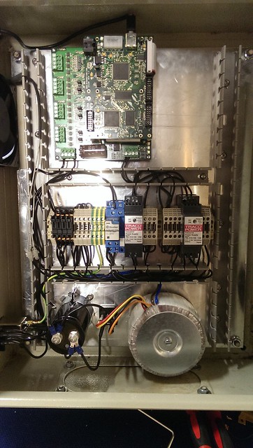

Wiring part 1 by mc_mtb, on Flickr

As it stands, all the internal wiring is pretty much complete. The only outstanding issue is I need to find the bleed resistor for the stepper power supply...
I only started out with a rough wiring diagram without too much thought towards wire routing, which is why the right hand trunking is empty, and will most likely stay that way. Thankfully there was just enough DIN rail for mounting all the bits on.
For those looking to build a control box, I'll run through what's on the rail, starting at the left.
240V positive distribution, consisting of one terminal, and four fuse holders (TX, 24V PSU, 5V PSU, Cooling Fan)
240V neutral distribution, consisiting of 4 terminals.
GND block. This acts as the star point for all GNDs/cable sheilding.
Emergency Stop relay. Given this is only a probe, and I have no intention of using it with a spindle, I opted for a basic E-stop system. The relay is powered by 24V via a single E-stop button, with the relay controlling the power to the transformer, and also the second contacts disabling an input to the KFlop, so it gets notified to stop.
24V PSU. This is just a basic DIN rail mounted switched mode power supply. This is probably the cheapest way to buy a regulated 24VDC for control purposes, and I love the fact it just clips on a bit DIN rail, without faffing with even more screws/brackets.
24V postive distribution.
Clamping block simply to create an obvious gap.
24V & 5V negative distribution. Both supplies have thier negatives connected together, and it gets ditributed from these terminals.
5V PSU. Definetly not the cheapest way to get a 5V supply, however I'm willing to pay for the convenience.
E-Stop connection terminals. As this build will only have one E-Stop button and nothing else that can trigger an E-stop, these aren't really needed. However they provide a convenient way of quickly bypassing the E-stop circuit.

This is definetly not a typical hobbyist type of build, but I wouldn't go as far as calling it an industrial build, as it is lacking in a couple safety related areas.

I have powered it all up. The fan spins, the 24V and 5V PSUs light up, the KFlop blinks into life, and the stepper supply magics up 45VDC when the E-stop circuit is completed, so all is good so far. Next step is what I class the external wiring, which is basically all the wiring that leaves the control box and connects to the machine, such as the stepper motors and the probe.
This machine isn't getting any limit or home switches. Position repeatability between power offs isn't a concern, so accurate homing isn't needed, and the machine won't have enough power to do any damage if it runs into the end of travel!

Offline mc

*
  •  382 382
    • View Profile
Re: A Wee Prober
« Reply #5 on: August 03, 2014, 07:51:48 PM »
I got a few hours work done on this tonight.
First up was mounting the stepper motors on the machine, then replacing the standard unsheilded cable with new CY cable -

Wiring Part 2 underway by mc_mtb, on Flickr

This is with the new  motor cables in place, just needing connected to the KStep. To connect the wires at the steppers, for now I've crimped them together using what crimps I had available. Ideally I'd use butt crimps with some heat shrink to keep everything sealed, but this will do for now.
After connecting everything to the KStep, the laptop was attached, and movement tested using KMotion (Dynomotion's software that allows you to directly access the KFlop for configuration/testing purposes).
The motor settings were then copied into the required initialisation file, and Mach was quickly configured with the required motor tuning details. After a few tweaks of settings, the axis were all going the right directions, so the mandatory RoadRunner file was run, and you can now waste 25 seconds of your life watching it on youtube - http://youtu.be/BON4GpJmobU

Main thing left to do now, is mount and connect up the probe.
Here's the first stage -

Bit Aluminium by mc_mtb, on Flickr

Wiring in the probe is going to involve a bit circuit board creation, which I'll save for the next progress post.

Offline mc

*
  •  382 382
    • View Profile
Re: A Wee Prober
« Reply #6 on: August 04, 2014, 06:52:08 PM »
So the probe is designed to work with an input using 5V with a 4k7-10k ohm pull-up or pull-down resistor, and the KStep requires 12-24V to power the 10k ohm optos. After a couple quick calculations, using 5V and a 4k7 resulted in the probe switching ~1mA, whereas even at 12V the optos would need ~1.2mA, or ~2.4mA at 24V. I was more concerned about the higher voltage reducing the probe life, so a solution was needed -

Strib board. The saviour of electronic bodges by mc_mtb, on Flickr

The board on the left is the solution, using what parts I had on hand. The end result is the probe having to switch ~0.9mA at 5V.
The solution could of been simpler, as I could of bypassed the optos, and used one of the 5V tolerant LVTTL inputs directly on the KFlop, however I prefer keeping logic power supplies seperate from control/machine wiring.
The board takes 24V, drops it down to 5V using a simple linear regulator, then uses a NPN transistor to switch the opto input to the KStep to GND, via the probe and a 4k7 resistor. I also added a couple LEDs, one so I know it's powered up, and one so I know when the probe circuit is complete. When the probe isn't active, the opto/input is active, so should a fault develop, the circuit should be broken and everything stops.

One little bodge I like, is the 7805 regulator should have a tantalum, mylar or similar low internal resistance capacitor mounted as close as possible to the input leads, when it is mounted at a distance from the power source. Now given I don't have any suitable through hole capacitors on hand, a solution was quickly found -

Mounted as closely as possible.. by mc_mtb, on Flickr

The only suitable capacitors I had, were surface mount ceramics, and you can't get any closer to the leads, than directly on them!
The capacitor is not big enough, so I coupled it with an electrolytic, which will handle the bigger ripples, and the ceramic should at least absorb some of the higher frequency ripples.


The other board on the right, was thrown together quickly to provide a basic breakout board to connect to the 26pin header on the KStep. After soldering on the header, I ran a thin dremel grinding disc between the two rows of pins. The 0.2" terminal blocks were spaced to allow access to the inner blocks, with the outer blocks staggered across one strip/0.1".

I ran out of time to get them mounted on the machine today, but it should be a quick job in the morning, along with putting the finishing touches to the probe holder, at which point probe testing can begin.

Offline mc

*
  •  382 382
    • View Profile
Re: A Wee Prober
« Reply #7 on: August 05, 2014, 07:24:15 PM »
First job today was finishing of the dummy spindle/probe holder -

Touch Prove Mount by mc_mtb, on Flickr

Nothing fancy, just a lump of round aluminium bar reduced to slightly smaller than the original spindle motor. Removing the motor took more force than what I'd expected, so the slightly smaller diameter means only the use of a single screwdrive to open up the clamp was needed along with hand pressure to get slide it in.

Then it was a case of installing the probe, along with the additional boards, connecting up the remaining wiring, and testing it out-

Calibration by mc_mtb, on Flickr

The only issue I had, was I forgot to change the allocated pin in the KFlop notify program, so despite the probe input showing as active in Mach, it never stopped movement during probing moves. However a quick edit of the code fixed that, and things worked as planned.
Initial attempts at probing aren't that good for fine details, but I still need to measure and set the backlash for the axis, so that will be tomorrows job.

Offline mc

*
  •  382 382
    • View Profile
Re: A Wee Prober
« Reply #8 on: August 22, 2014, 07:16:43 AM »
Now I'm back after a week enjoying some french mountains, I'm back to getting this working how I'd like it to.

Initial attempts at probing were not ideal for the level of detail I'm looking for, so after a bit fettling with the mechanics, the only major issue I came across were the 698 bearings which are used as thrust bearings for the ballscrews, were absolutely rubbish. Using standard bearings for thrust bearings is pretty poor practise, but given the loads of this machine, some good quality ones have solved the roughness issues.
However accuracy still hasn't been that great, despite minimal measurable backlash.

So this package turned up yesterday -

More Bits by mc_mtb, on Flickr

And I've just finished doing some soldering-

More Wiring by mc_mtb, on Flickr

I've got to head of just now, but I'll hopefully get everything mounted later tonight, and post up the details.

Offline mc

*
  •  382 382
    • View Profile
Re: A Wee Prober
« Reply #9 on: September 01, 2014, 07:27:17 PM »
After a bit longer than planned, the extra additions are now installed and working.


X Glass Scale by mc_mtb, on Flickr


Y Glass Scale by mc_mtb, on Flickr

As I mentioned in the previous post, accuracy wasn't quite as good as I had hoped relying solely on open loop stepper control, so I needed to close the loop. Now one of the other reasons I opted for a KFlop, is it's flexibility, and the ability to easily close the loop by adding suitable encoders or scale, so a couple micron accuracy glass scales were purchased. The main reason for the scales, is the fact they directly measure the axis position, whereas an encoder only measures the motor position so is still affected by any backlash in the system.

Using the cable from my previous post, it was a simple case of wiring the cable in, a not quite so simple case of mounting the scales, plugging the scales in, changing a couple settings within the KFlop initialisation so it knew there were now encoders fitted and to run in closed loop stepper mode, then finally a quick change to the kflop probe notification program so the actual position was returned from the scales and not the commanded stepper position.

After that, the probing accuracy has greatly improved, and I now just need to iron out the kinks in my workflow from probed sample to machined copy.