Welcome, Guest. Please login or register.
Did you miss your activation email?
May 28, 2012, 10:07:41 AM

Login with username, password and session length
Search:     Advanced search
* Home Help Search Calendar Links Login Register
+  Machsupport Forum
|-+  Mach Discussion
| |-+  General Mach Discussion
| | |-+  Mach3 vs NC-studio
Pages: 1   Go Down
Print
Author Topic: Mach3 vs NC-studio  (Read 472 times)
0 Members and 1 Guest are viewing this topic.
jallitt
Active Member

Offline Offline

Posts: 44


View Profile
« on: November 07, 2011, 12:32:52 AM »

seems like a lot of routers out of China come with NC-studio which uses a PCI card to control the machines via a 15 pin cable.

I just picked up a used 1200x1200 machine with the aforementioned NC-studio and got it running and did a test cut with the last tool path I ran on a smaller mach3 controlled 500x300 machine and it was quite disappointing - lots of dwell marks and odd lines in the surface - admittedly this was a 1/72 scale model plane part which isn't what the machine was designed for but I figured it should be able to do a bit better.

So I wired a Mach compatible breakout board to  some ribbon cable hooked up to a 15 pin D connector (so I didn't need to modify anything in the machine), set up and tuned the motors (7000mm/min rapids which is pretty good and maybe a bit fast) and re-ran the part. It's basically identical to the part made on my smaller machine.

Here's a comparison pic -


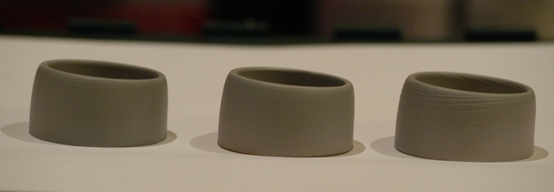
Mach/smoothstepper 500x300 machine on the left, Mach on the 1200x1200 machine in the middle, NC-studio on the 1200x1200 machine on the right.

The results speak for themselves and I'll be permanently wiring in the mach breakout board...
Logged
Tweakie.CNC
Active Member

Offline Offline

Posts: 3,263


Super Kitty.


View Profile WWW
« Reply #1 on: November 07, 2011, 02:58:47 AM »

So how exactly have you wired the breakout board to the 15 pin connector ??

Tweakie.
Logged

Success consists of going from failure to failure without loss of enthusiasm.  Winston Churchill.
jallitt
Active Member

Offline Offline

Posts: 44


View Profile
« Reply #2 on: November 07, 2011, 04:17:38 AM »

The router has a simple breakout board with a 15 pin connector on it. The NC-studio PCI card just has 3 sets of step/dir signals, 3 outputs to control the VFD speed, and 3 limit switch inputs so I just traced the wiring and have the mach breakout board between the parallel port and a 15-pin connector like this:


I didn't want to start disconnecting wires in the machine until I was sure this would work. Wasn't 100% sure I'd be able to start the spindle the way the VFD is configured.

Now that I know where all the wires go I can replace the 15-pin BOB in the machine with the parallel port BOB.
Logged
Tweakie.CNC
Active Member

Offline Offline

Posts: 3,263


Super Kitty.


View Profile WWW
« Reply #3 on: November 07, 2011, 04:44:10 AM »

Thanks, I think I understand what you have done now.

Tweakie.
Logged

Success consists of going from failure to failure without loss of enthusiasm.  Winston Churchill.
Pages: 1   Go Up
Print
Jump to:  

Powered by MySQL Powered by PHP Powered by SMF 1.1.16 | SMF © 2011, Simple Machines Valid XHTML 1.0! Valid CSS!